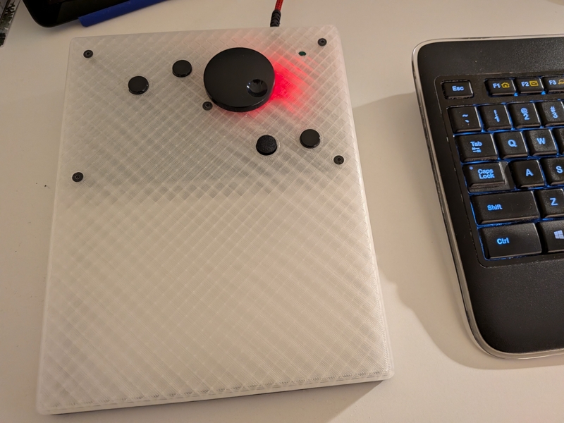
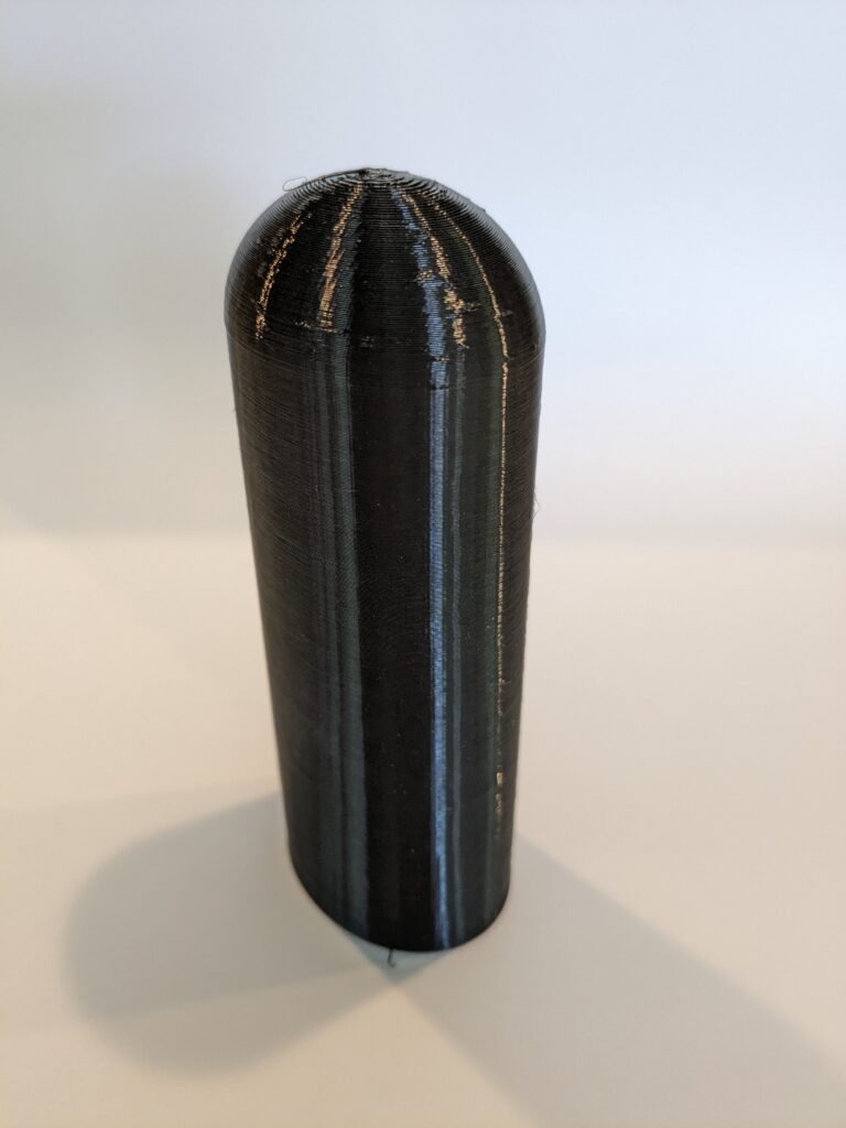
It lived in a wooden frame for five years before I got around to 3D printing a proper enclosure. Still working just fine six years later.
There’s no bottom cover. Top is PLA and the bottom edge has a shallow dove-tail I used to snap in a bit of printed TPU trim that makes it non-skid. Cntrl button to the right of the thumb wheel was added after I noticed how often Cntrl-clicks were required.
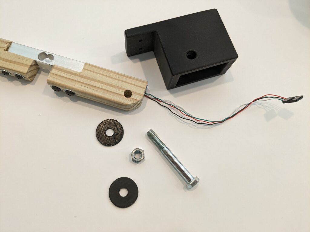
I finally got ’round-tuit. I’d picked up a 10kg load cell and HX711 load cell amplifier from SparkFun a couple of years ago, but as is often the case, multiple other shiny new projects grabbed my attention. The lack of an easy way to fabricate many of the parts had something to do with not getting ’round-tuit as well.
So, now that I’ve a 3D printer, I decided it was time to retire the trusty old handbrake I’d built back in 2019 and build a new one.
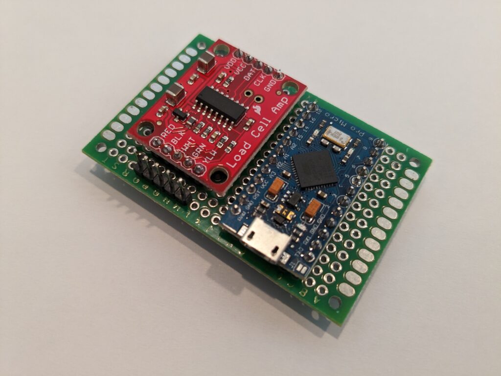
I soldered up the HX711, a HiLetgo Pro Micro Arduino clone (Arduino Leonardo board in the IDE), and a header for the load cell onto protoboard… and made the first mistake.
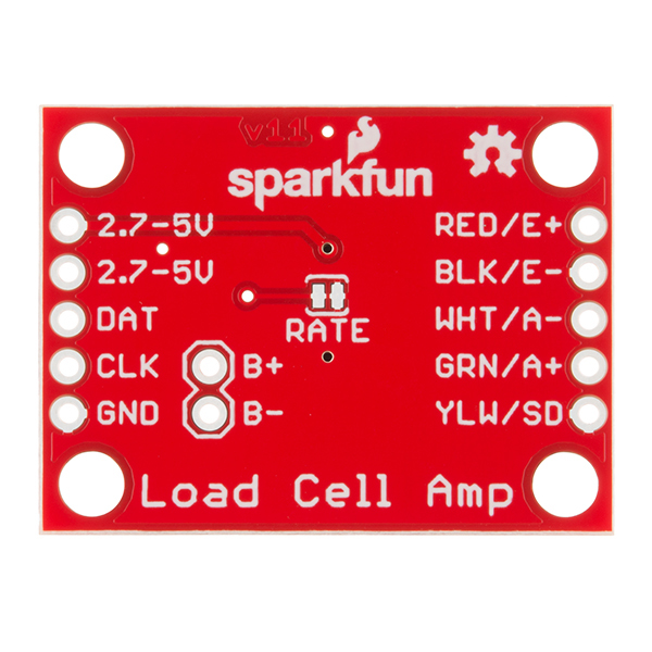
The HX711 ships jumpered to run at 10 Hz, which is fine for a scale, but way too slow for a handbrake. See that trace right above where it says “RATE”. Well, it needs to be cut to run the HX711 at 80 Hz. So, rather than desolder everything, I very carefully drilled a hole through the back of the protoboard and cut the trace. Don’t do it this way – much easier to cut it first. <g>
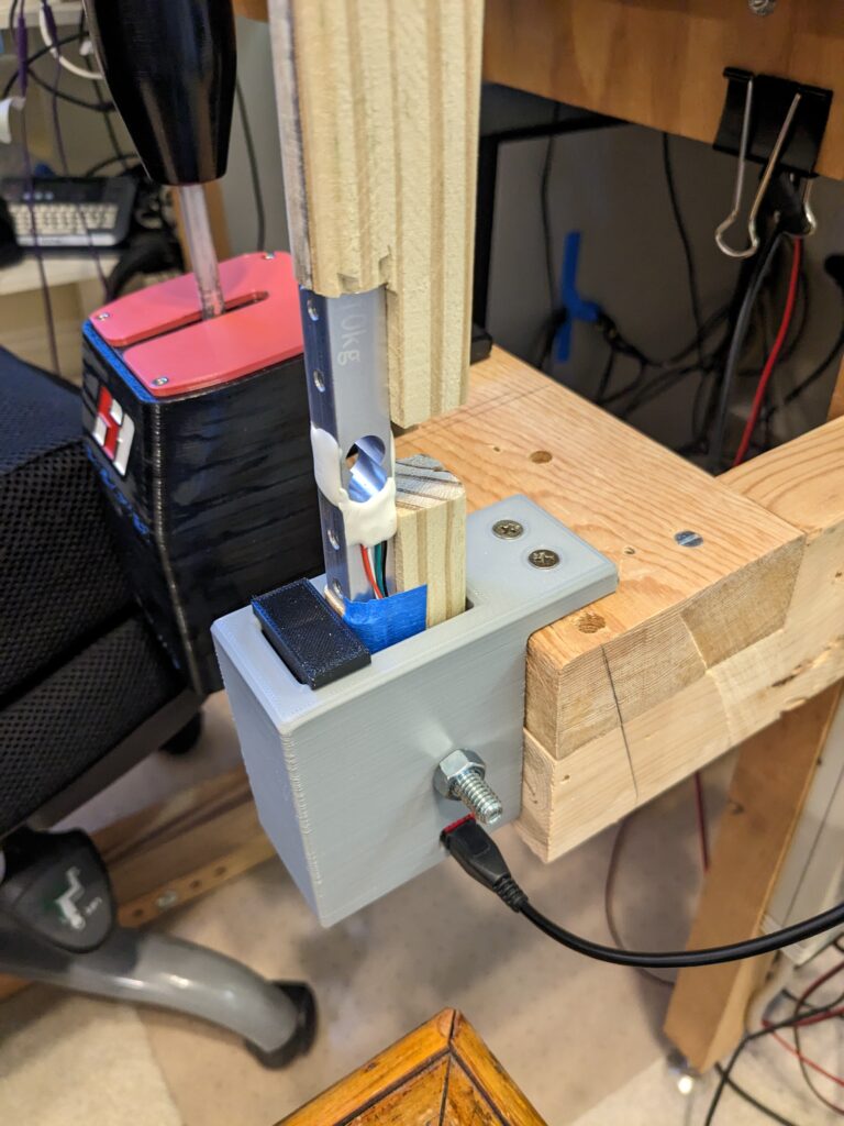
Next, I designed a test base, attached the load cell to a piece of wood, and bolted it to the rig to see if it was strong enough. Nothing broke, so I proceeded to write the code.
Testing setup
The code is nothing fancy, just used the MHeironimus Arduino joystick library and the bogde HX71 libraries. Read data, scale it, ignore low level noise, and send to the PC when the value changes.
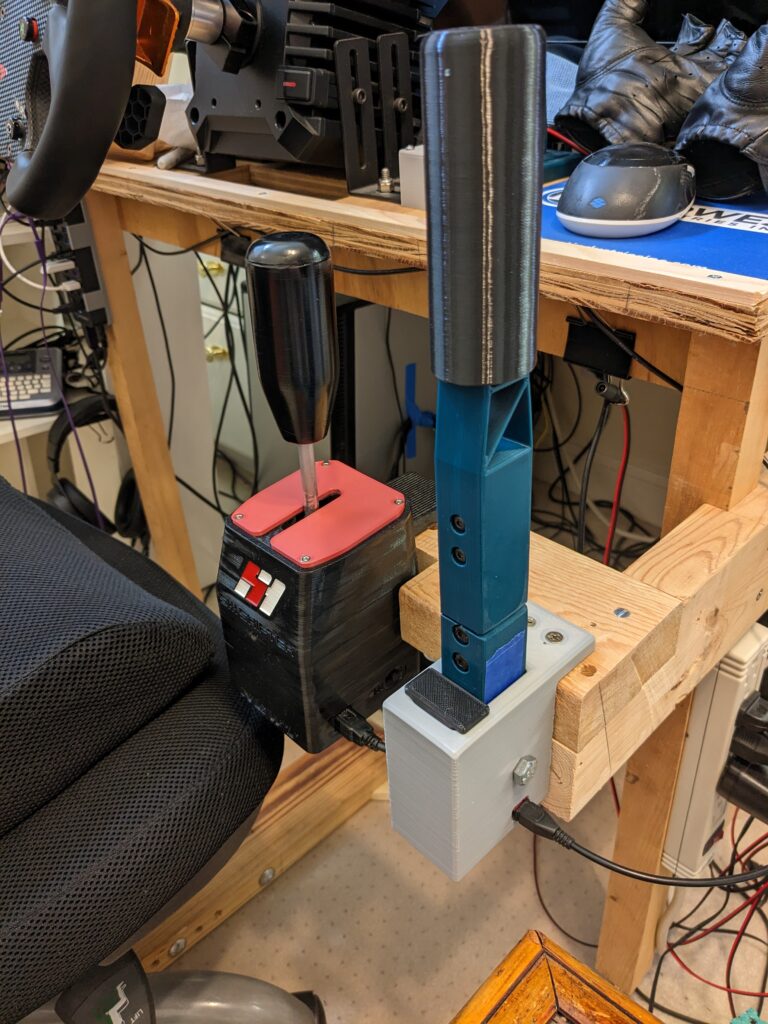
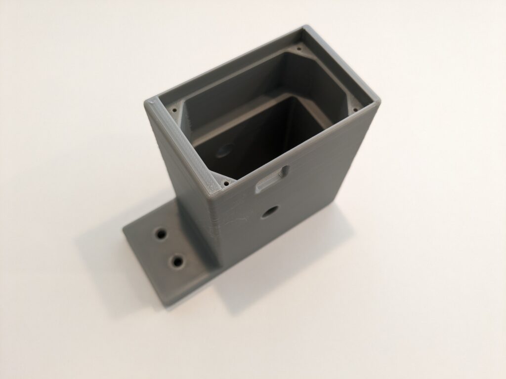
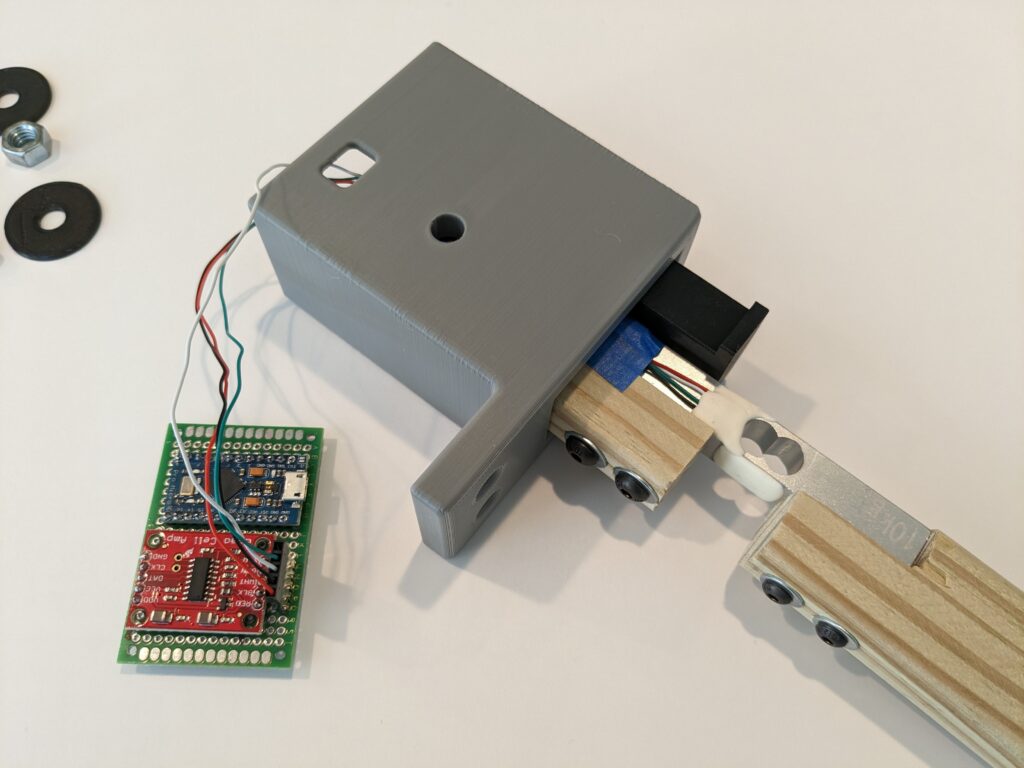
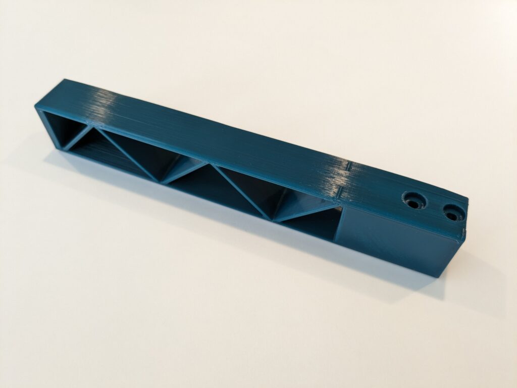
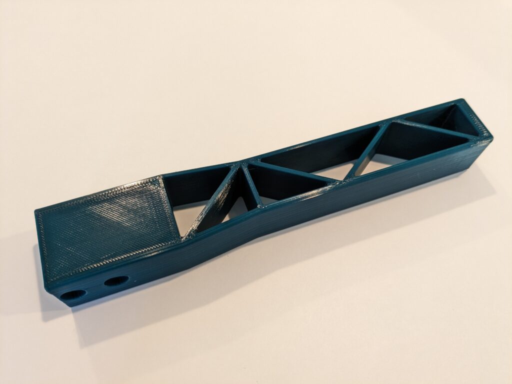
With the code and the test base working I got to designing the final base and lever. The final base included a place to mount the PCB.
Base with PCB mount
Rather than use a spring, I printed a block of TPU which goes in front of the lever. I printed a few, changing the print density until I liked the amount of squish it provided.
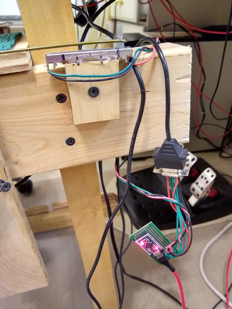
Test rig
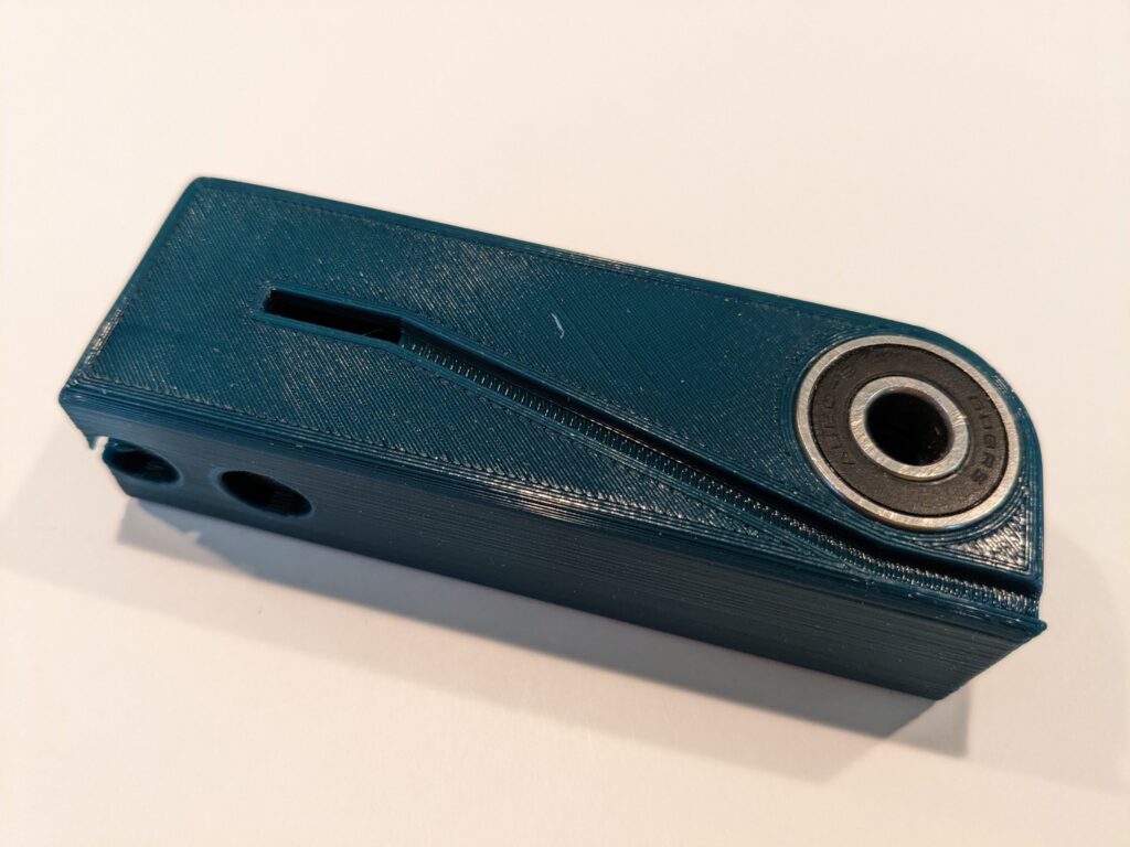
The Lever
The lower part of the printed lever has a pair of press fit 608 skateboard bearings on either side to spread the load. The groove down the side is for the load cell wiring. The opening to the inside is wide enough to slip the five pin Dupont connector through.
Press fit bearings in vise
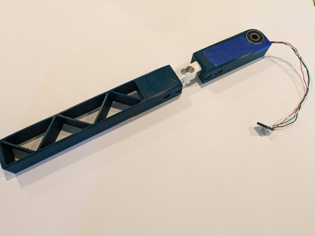
I decided the first upper lever was a bit too bulky and a bit too tall, so I made another with some taper that was a bit shorter.
Original upper lever
Tape covers wire – will hot glue later
Slimmer upper handle
The holes on the countersink side are supposed to be clearance holes. Depending on how it prints, you may have to chase them with a reamer or drill. The holes on the far side from the countersinks are supposed to be tight enough that they are threaded by the screws.
Designed and printed a grip in TPU. The grip for the first lever had a domed top, which I decided I didn’t care for, so I made the grip for the slim lever flat on top.
Did not like the domed top
Code
The code is quite simple. All the heavy lifting is done in the joystick and HX711 libraries. You can get a copy here – Analog-E-Brake-Load-Cell
You may be happy with the settings I used for SCALE_FACTOR and NOISE, but to determine these yourself just build with DEBUG and CALIBRATE defined. I’d initially set NOISE to 10, but discovered that the vibration of the rig while driving was enough to generate readings as high as 150, so I bumped that up to 250.
// Analog eBrake-Handbrake using hx711 to read load cell

// #define DEBUG
// #define CALIBRATE

#include "Joystick.h"	// https://github.com/MHeironimus/ArduinoJoystickLibrary
#include "HX711.h" 		// https://github.com/bogde/HX711

#define LOADCELL_DOUT_PIN  3
#define LOADCELL_SCK_PIN  2

HX711 scale;

// max joystick (32767) divided by max HX711 reading (1,000,000) by experiment
#define SCALE_FACTOR	0.032767

// noise level determined by experiment, DEBUG & CALIBRATE defined
#define NOISE 		250

#define BUTTONS		0
#define HATS		0

Joystick_ Joystick(JOYSTICK_DEFAULT_REPORT_ID, JOYSTICK_TYPE_JOYSTICK, BUTTONS, HATS,
	false, false, false, false, false, false, false, false, false, true, false);
//  X      Y      Z      Rx     Ry     Rz     Rudder Throt  Accel  Brake  Steering

long offset;

void setup()
{
	Joystick.setBrakeRange(0, 32767);
	Joystick.begin();
	#if defined(DEBUG)
	Serial.begin(115200);
	#endif

	scale.begin(LOADCELL_DOUT_PIN, LOADCELL_SCK_PIN);

	offset = scale.read_average(10);	// zero out offset at startup

	Joystick.setBrake(0);		// start at zero brake
}

#if defined(CALIBRATE)
	long reading = 0;
#endif

long lastVal = 0;

void loop()
{
	if (scale.is_ready()) {
		long mapped = (long)((float) (abs(scale.read() - offset)) * SCALE_FACTOR);

		if (mapped > 32767)
			mapped = 32767;

		#if defined(CALIBRATE)
		/* calibration:
		 NOISE
		 Power up with no pressure on the cell, wait a bit and record the noise level. Note
		  that it is very sensitive - it will pick up vibrations of your rig. You might wish
		  to drive a bit with the calibration code running. Update NOISE value.

		 SCALE_FACTOR
		 Apply reasonable pressure on lever. If it maxes out (32767) too easily change
 		 SCALE_FACTOR to bring it in range.
		*/
		if (mapped > reading) {
			reading = mapped;
			Serial.print("Value: ");
			Serial.println(reading);
		}
		#else
		if (mapped <= NOISE)
			mapped = 0;
		if (lastVal != mapped) {		// don't transmit data unless changed
			Joystick.setBrake(mapped);
			lastVal = mapped;
		}
		#endif
	} else {
		delay(1);
	}
}
Parts
60 x 40 mm proto PCB
HiLetgo Arduino Pro Micro clone (https://tinyurl.com/3md9wk75)
Was just reminded why I tell everyone to avoid GoDaddy like the plague. Aside from the fact that it took two hours with tech support to forward a domain, and the chat interface repeatedly timing out (even while I was typing to tech support) forcing me to keep refreshing it, there is a much more troubling issue.
Their security is absolutely atrocious!
On the way to the ridiculously long interaction with tech support, their system became suspicious of my logging in with five different browsers trying to get a simple domain forward to work, and began requiring I provide a confirmation number which they forwarded to the contact email address on record. Fine and dandy.
What isn’t so fine and dandy is that the email address on record was used as contact on more than one GoDaddy account. Now, there’s normally nothing wrong at all with using your email address on more than one account, but I would caution against it on GoDaddy.
I entered credentials for the account, had GoDaddy send the confirmation number, entered the number, and was logged into a COMPLETELY DIFFERENT ACCOUNT… Yes, they gave me complete control of someone else’s account.
Without entering ANY of the credentials for the other account!
I’ve been doing some hand tool woodworking lately. Been getting by with a rubber mallet for the chisel work, but then I saw Rex Kruger’s video on building a traditional joiners mallet and decided that’s what I needed.
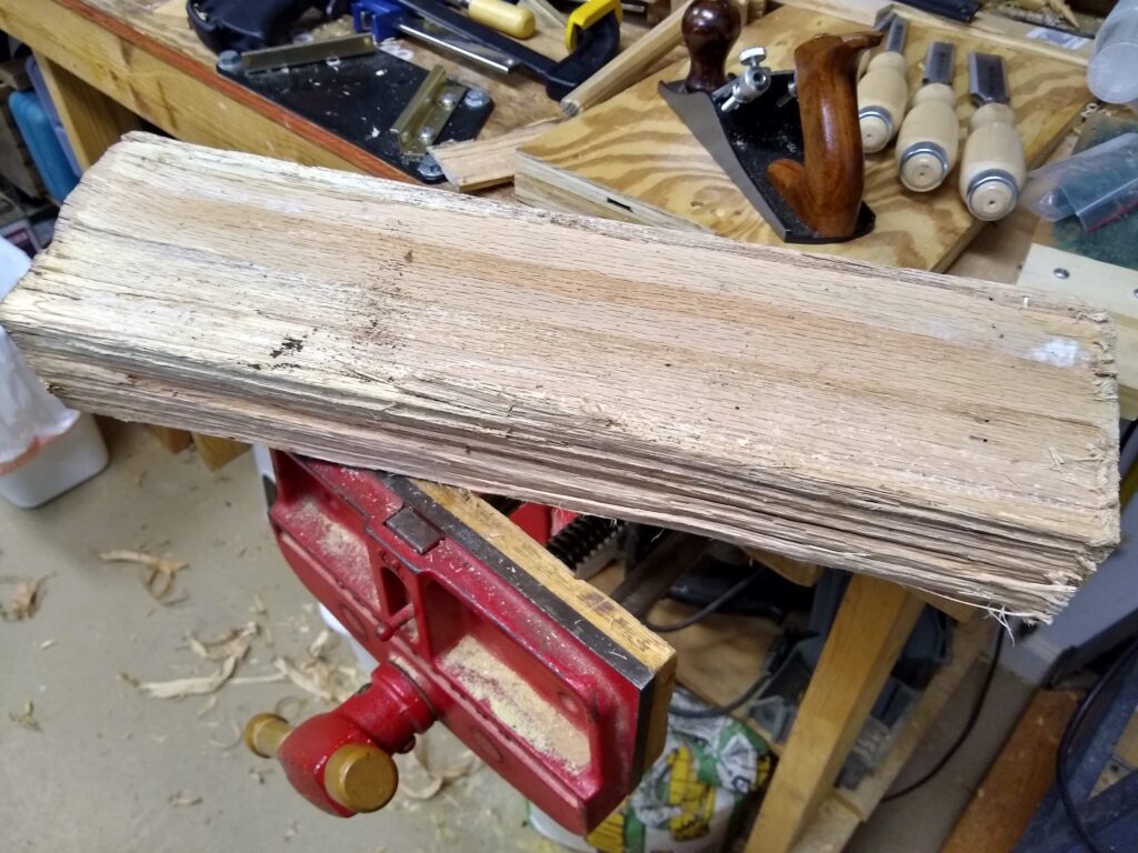
Step one: Grab a piece of firewood off the pile.
Nice bit of straight-grained oak firewood
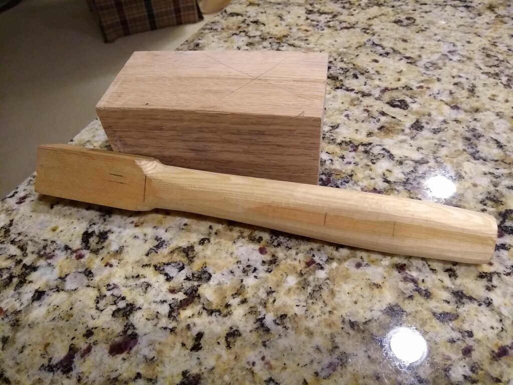
Step two: Make a mallet head.
Simple, but it took a bit of time to turn that into this. A whole bunch of hand sawing and planing later I have a blank that’s square.
Squared up blank
This is the point where I noticed how wet the wood was. This blank sat on a shelf for several weeks drying… until I got impatient and used it anyway. It had developed some checking as it dried, which I ignored. It’s only firewood. I can make another.
I grabbed a piece of 1×2 mystery wood I had lying around for a handle. A bit of work with the spoke shave and I had something that felt comfortable in my hand.
A comfortable handle
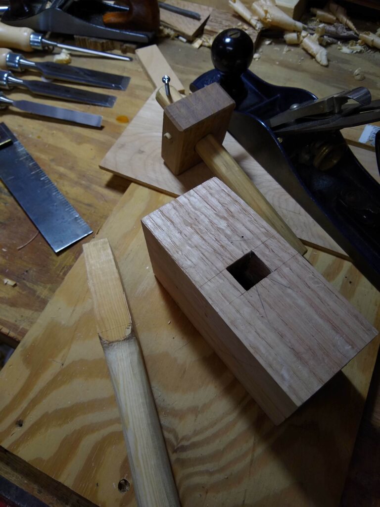
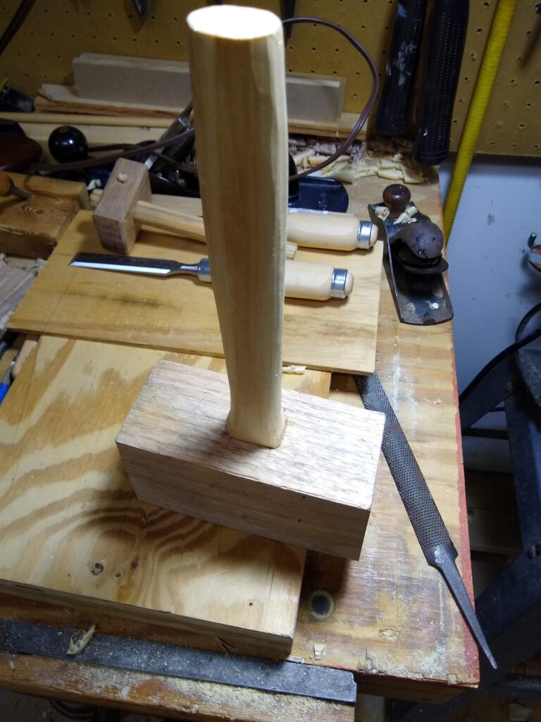
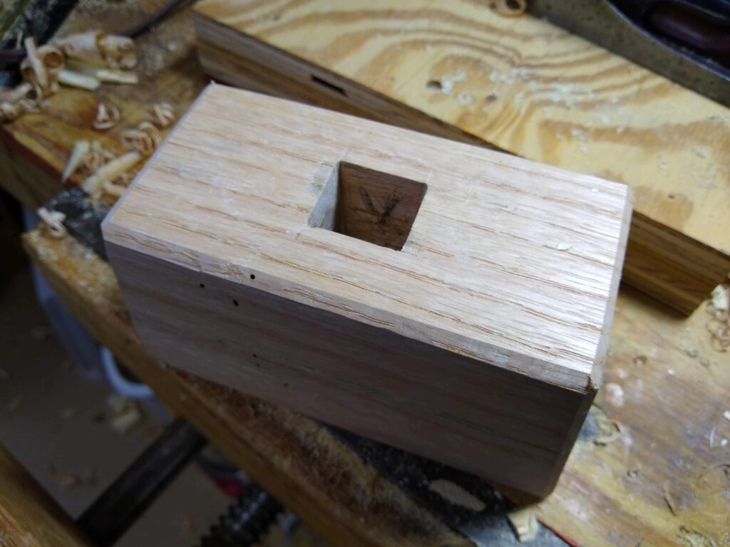
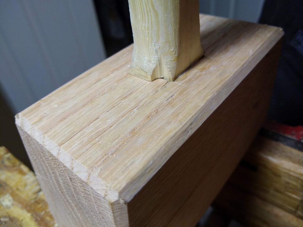
The mortise was made with a power drill and then chiseled square. There’s actually a slight taper to both handle and mortise.
Mallet head mortised
A bit more work and the handle fit nicely.
Handle fitted
The faces were then cut at a shallow angle, which places the face of the mallet head square with the chisel when it’s struck. All the edges of the mallet head were chamfered.
Mallet head ready to attach the handle
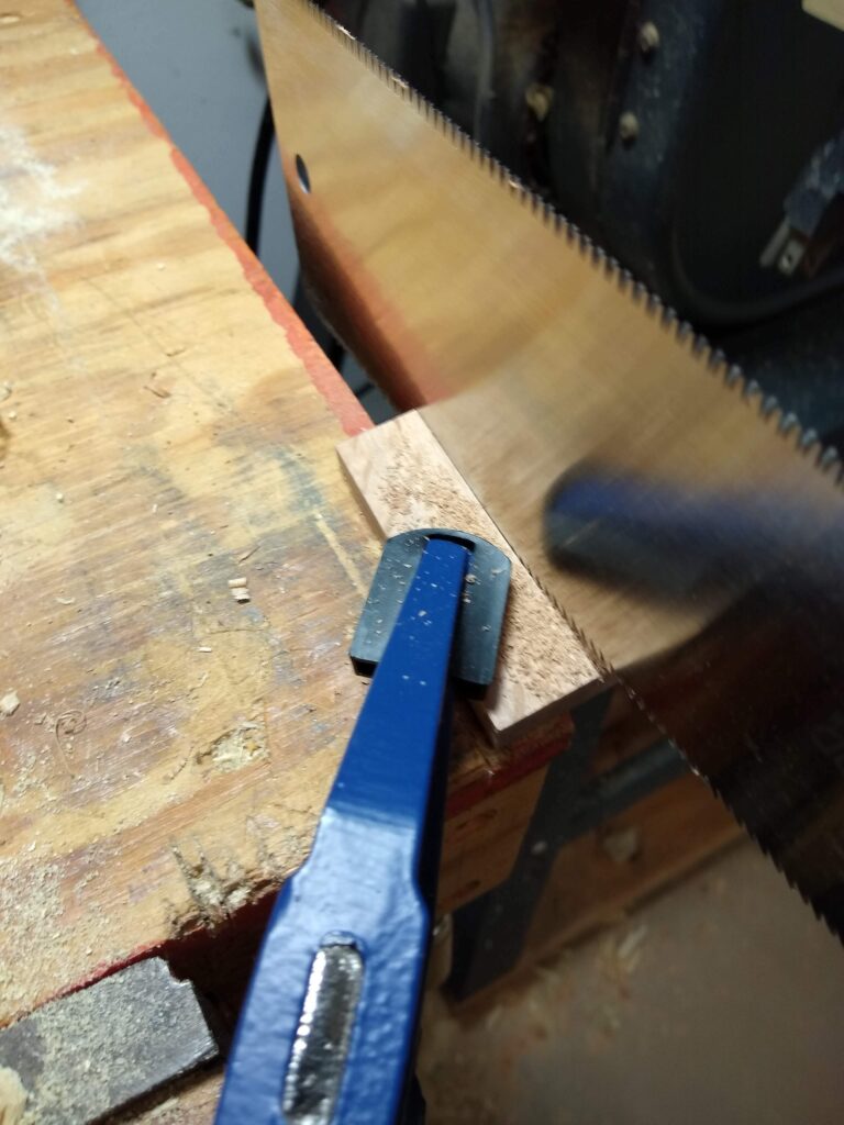
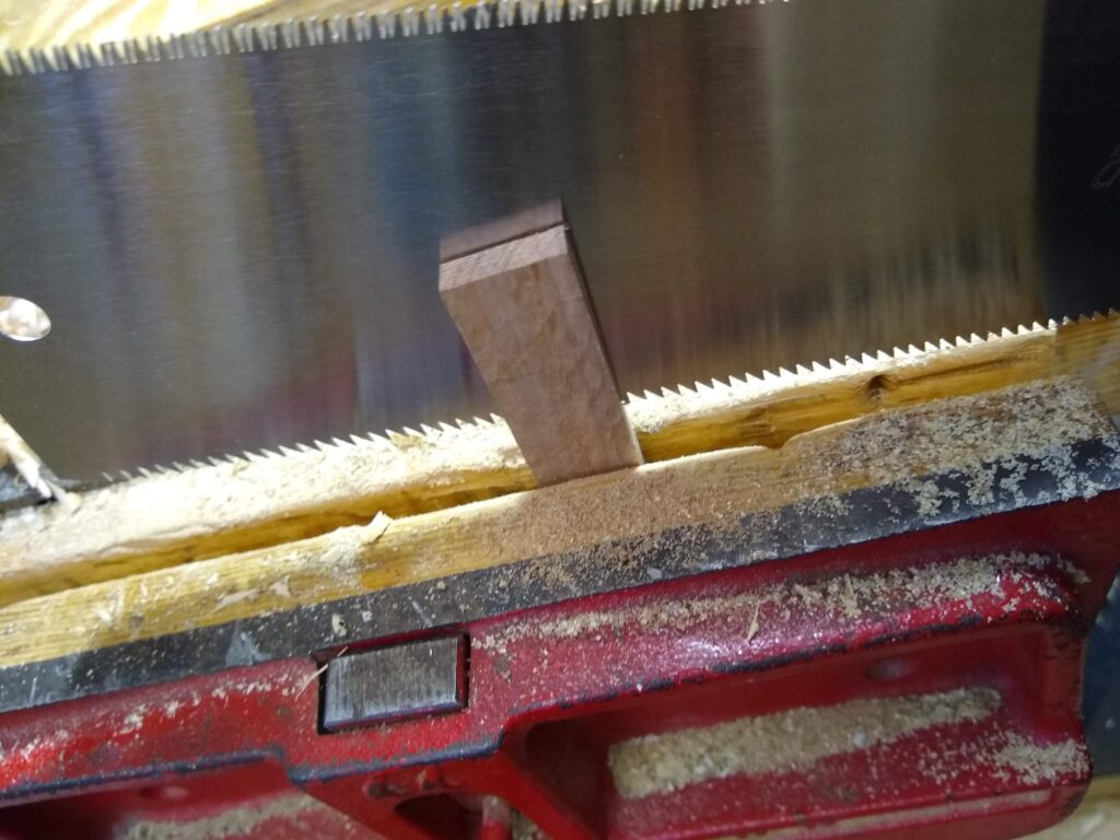
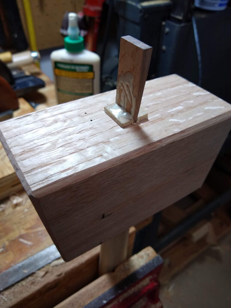
I used some persimmon to make the wedge.
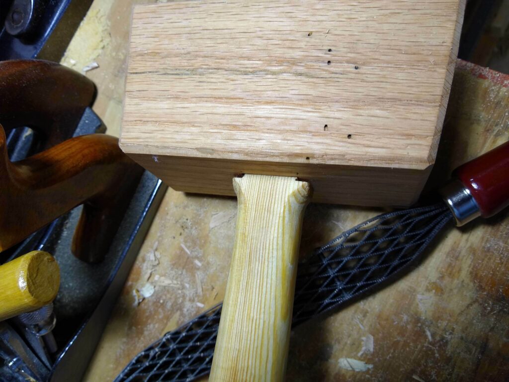
Drove the handle all the way into the head with some glue. I got a wee bit carried away seating the handle and chipped off a bit of the shoulder. Unfortunately, I did not notice this until much later, so the piece was lost amongst the chips and sawdust on the floor.
Handle set in mallet head
Then applied glue to the wedge and drove it in.
Installing the wedge
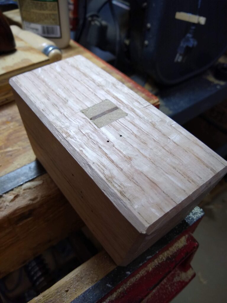
Once the glue dried it was cut and planed flush.
Finished handle installation
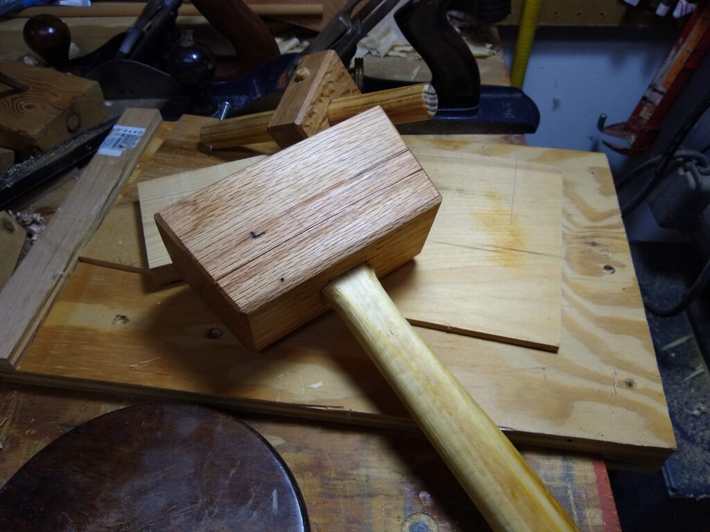
Gave it a good helping of boiled linseed oil, and… it’s a mallet.
Finished mallet
The checking that developed while it was drying has not gotten any worse, though if you look at the next photo you can see the head has shrunken noticeably since it was installed. Doesn’t affect it’s performance in the slightest.
Visible shrinkage
Mallet works great. This oak is hard stuff. I’ve been using it for months and the faces still look like I just finished planing them.
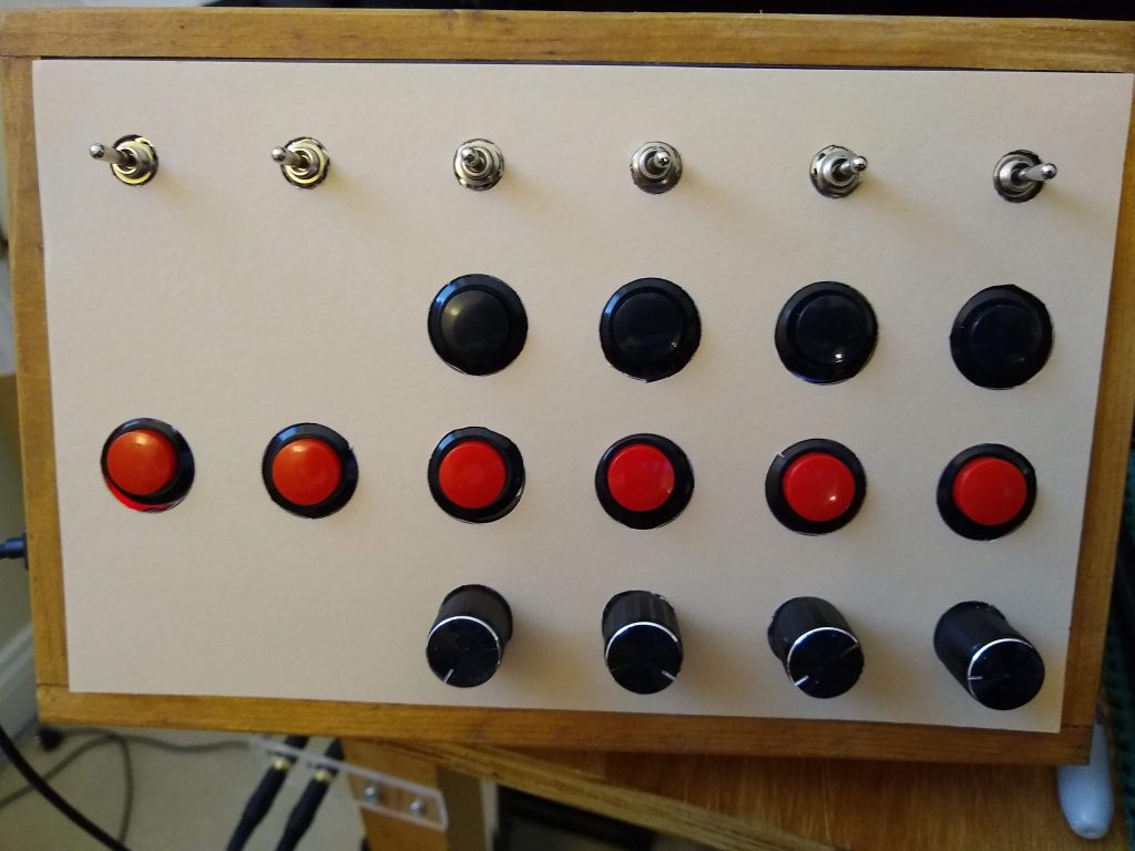
Still just as unexciting to look at, but with more buttons!
I just saw an ad for one of the commercial button boxes and they listed a great new feature – get more outputs from the rotary encoders by using their push buttons as shift keys. A great addition to my original button box.
As I’d recently been thinking about wanting more rotary encoders and having more buttons than I knew what to do with, I thought it was a great idea to sacrifice four of the buttons to get four more rotary encoders.
It was just a simple matter of tracking the state of the four buttons and using that info to send different codes for the encoders if they were pressed. I’m still sending the button presses as well, so I can still choose whether to use the extra encoders or the buttons when I assign the buttons to controls in game.
There’s not all that much to doing a button box, so I’ll just publish the code here.
//BUTTON BOX
//USE w ProMicro
//Tested in WIN10 + Assetto Corsa
//AMSTUDIO
//20.8.17
// YouTube video: https://www.youtube.com/watch?v=Z7Sc4MJ8RPM

// 10/06/2019
// Bill Smithem
// Added additional button
// 4/4/2020
// Bill Smithem
// set debounce time to 50 (default was 10)
// 01/21/2021
// Bill Smtihem
// add "4 func" rotaries - different code sent if button pressed while turning. Tracked state of buttons 21-24
//  and used that to "shift" the rotary encoders. Note: we're still sending the button presses for the rotary
//  encoders, so mind that when assigning buttons in game.
// Number of "buttons" goes from 33 to 41

#include <Arduino.h>
#include <Keypad.h>
#include <Joystick.h>

#define ENABLE_PULLUPS
#define NUMROTARIES 4
#define NUMBUTTONS 25
#define NUMROWS 5
#define NUMCOLS 5

// Odd map is so buttons come out in numerical order, not scanning order. i.e. top left button is one, next is
//  two, etc. Just wired in the most convenient fashion and worked it out in the map.
byte buttons[NUMROWS][NUMCOLS] = {
  {5, 6, 17, 23, 12},
  {3, 4, 16, 22, 11},
  {9, 10, 19, 20, 14},
  {1, 2, 15, 21, 0},
  {7, 8, 18, 24, 13},
};

struct rotariesdef {
  byte pin1;
  byte pin2;
  int ccwchar;      // send this for CCW
  int cwchar;       //  this for CW
  int ccwPchar;     //  this for CCW with button pressed
  int cwPchar;      //  and this for CW with button pressed
  volatile unsigned char state;
};

rotariesdef rotaries[NUMROTARIES] {
  {0, 1, 32, 31, 40, 39, 0},
  {2, 3, 29, 30, 38, 37, 0},
  {4, 5, 27, 28, 36, 35, 0},
  {6, 7, 25, 26, 34, 33, 0},
};

#define DIR_CCW 0x10
#define DIR_CW 0x20
#define R_START 0x0

#ifdef HALF_STEP
#define R_CCW_BEGIN 0x1
#define R_CW_BEGIN 0x2
#define R_START_M 0x3
#define R_CW_BEGIN_M 0x4
#define R_CCW_BEGIN_M 0x5
const unsigned char ttable[6][4] = {
  // R_START (00)
  {R_START_M,            R_CW_BEGIN,     R_CCW_BEGIN,  R_START},
  // R_CCW_BEGIN
  {R_START_M | DIR_CCW, R_START,        R_CCW_BEGIN,  R_START},
  // R_CW_BEGIN
  {R_START_M | DIR_CW,  R_CW_BEGIN,     R_START,      R_START},
  // R_START_M (11)
  {R_START_M,            R_CCW_BEGIN_M,  R_CW_BEGIN_M, R_START},
  // R_CW_BEGIN_M
  {R_START_M,            R_START_M,      R_CW_BEGIN_M, R_START | DIR_CW},
  // R_CCW_BEGIN_M
  {R_START_M,            R_CCW_BEGIN_M,  R_START_M,    R_START | DIR_CCW},
};
#else
#define R_CW_FINAL 0x1
#define R_CW_BEGIN 0x2
#define R_CW_NEXT 0x3
#define R_CCW_BEGIN 0x4
#define R_CCW_FINAL 0x5
#define R_CCW_NEXT 0x6

const unsigned char ttable[7][4] = {
  // R_START
  {R_START,    R_CW_BEGIN,  R_CCW_BEGIN, R_START},
  // R_CW_FINAL
  {R_CW_NEXT,  R_START,     R_CW_FINAL,  R_START | DIR_CW},
  // R_CW_BEGIN
  {R_CW_NEXT,  R_CW_BEGIN,  R_START,     R_START},
  // R_CW_NEXT
  {R_CW_NEXT,  R_CW_BEGIN,  R_CW_FINAL,  R_START},
  // R_CCW_BEGIN
  {R_CCW_NEXT, R_START,     R_CCW_BEGIN, R_START},
  // R_CCW_FINAL
  {R_CCW_NEXT, R_CCW_FINAL, R_START,     R_START | DIR_CCW},
  // R_CCW_NEXT
  {R_CCW_NEXT, R_CCW_FINAL, R_CCW_BEGIN, R_START},
};
#endif

byte rowPins[NUMROWS] = {21, 20, 19, 18, 15};
byte colPins[NUMCOLS] = {14, 16, 10, 9, 8};

Keypad buttbx = Keypad( makeKeymap(buttons), rowPins, colPins, NUMROWS, NUMCOLS);

Joystick_ Joystick(JOYSTICK_DEFAULT_REPORT_ID,
                   JOYSTICK_TYPE_JOYSTICK, 41, 0,
                   false, false, false, false, false, false,
                   false, false, false, false, false);

void setup() {
  void rotary_init();

  Joystick.begin();
  rotary_init();
  buttbx.setDebounceTime(50);
}

void loop() {
  void CheckAllEncoders();
  void CheckAllButtons();

  CheckAllEncoders();

  CheckAllButtons();

}

// keep state of last four buttons (ones attached to rotaries)
KeyState rbState[] = { RELEASED, RELEASED, RELEASED, RELEASED };

void CheckAllButtons(void) {
  int kc;

  if (buttbx.getKeys())
  {
    for (int i = 0; i < LIST_MAX; i++)
    {
      if ( buttbx.key[i].stateChanged )
      {
        kc = buttbx.key[i].kchar - 21;        // track state of buttons 21-24 (switches on rotaries)
        switch (buttbx.key[i].kstate) {
        case PRESSED:
        case HOLD:
          Joystick.setButton(buttbx.key[i].kchar, 1);
          if (kc >= 0)
            rbState[kc] = PRESSED;
          break;
        case RELEASED:
        case IDLE:
          Joystick.setButton(buttbx.key[i].kchar, 0);
          if (kc >= 0)
            rbState[kc] = RELEASED;
          break;
        }
      }
    }
  }
}

void rotary_init() {
  for (int i = 0; i < NUMROTARIES; i++) {
    pinMode(rotaries[i].pin1, INPUT);
    pinMode(rotaries[i].pin2, INPUT);
#ifdef ENABLE_PULLUPS
    digitalWrite(rotaries[i].pin1, HIGH);
    digitalWrite(rotaries[i].pin2, HIGH);
#endif
  }
}

unsigned char rotary_process(int _i) {
  unsigned char pinstate = (digitalRead(rotaries[_i].pin2) << 1) | digitalRead(rotaries[_i].pin1);
  rotaries[_i].state = ttable[rotaries[_i].state & 0xf][pinstate];
  return (rotaries[_i].state & 0x30);
}

void CheckAllEncoders(void) {
  for (int i = 0; i < NUMROTARIES; i++) {
    unsigned char result = rotary_process(i);
    if (result == DIR_CCW) {
      // check if button pressed
      if (rbState[3-i] == PRESSED) {
        Joystick.setButton(rotaries[i].ccwPchar, 1); delay(50); Joystick.setButton(rotaries[i].ccwPchar, 0);
      } else {
        Joystick.setButton(rotaries[i].ccwchar, 1); delay(50); Joystick.setButton(rotaries[i].ccwchar, 0);
      }
    }
    if (result == DIR_CW) {
      if (rbState[3-i] == PRESSED) {
        Joystick.setButton(rotaries[i].cwPchar, 1); delay(50); Joystick.setButton(rotaries[i].cwPchar, 0);
      } else {
        Joystick.setButton(rotaries[i].cwchar, 1); delay(50); Joystick.setButton(rotaries[i].cwchar, 0);
      }
    }
  }
}
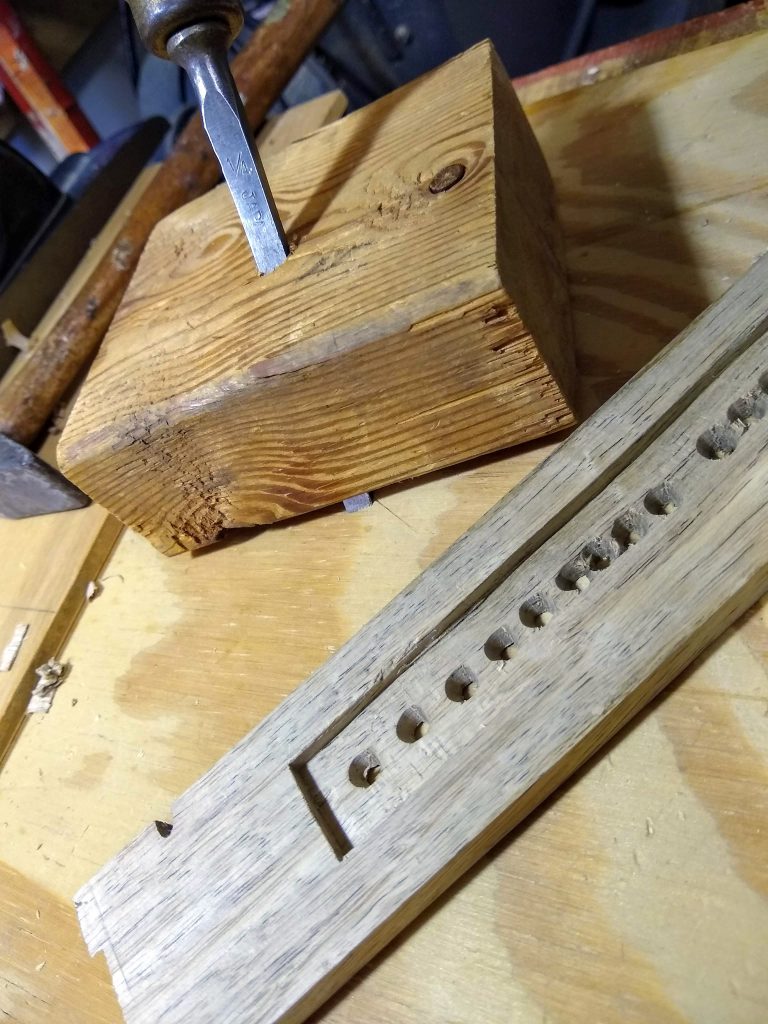
I was chiseling out a recess for an LED RPM display for my sim rig and realized trying to do it by hand with a chisel was just self torture, so I changed tactics and built another tool.
Nothing original here, I’ve seen it done multiple times, but it works great. I put an edge on an old beat up 1/4″ chisel, eyeballed the angle and drilled 1/4″ hole through a scrap bit of 2×4. Then pushed the chisel through the 2×4 whilst twisting it to cut a chisel-sized hole, and I had a working router chisel.
This works surprisingly well. Tap the back of the chisel with a light hammer to advance the chisel, tap the back of the block to move it backwards. Would have worked better if I’d chosen a flat bit of 2/4 (this piece has a pretty good warp in it), but it was good enough to get a consistent depth recess routed.
It worked so well I’ve added making a decent one to my ridiculously long to-do list. I may actually get round-tuit some day. 🙂
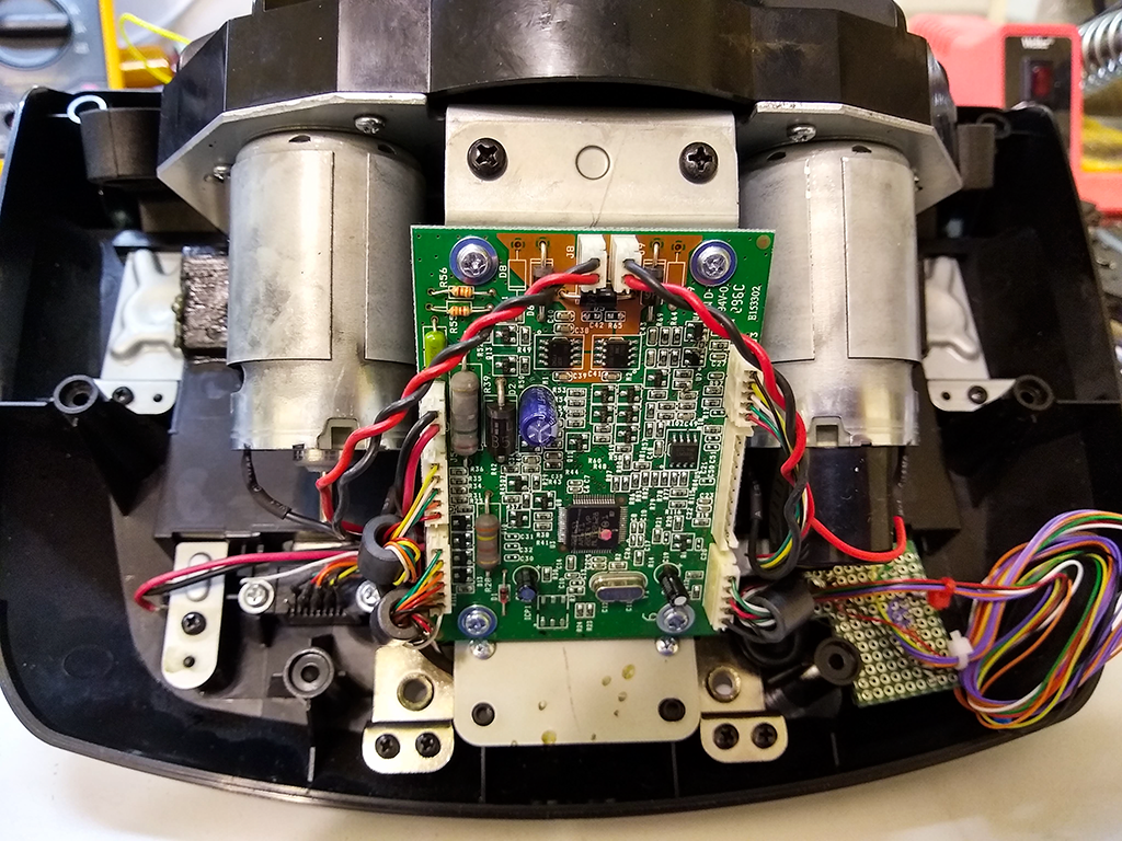
I’ve never been completely satisfied with my home brew button box. There’s nothing wrong with it, it works just fine, but hitting the wrong button or running off the road while looking for the right one was getting old, so I started designing a mod for my G25 (yeah, I know, ancient… mine is fourteen years old) to add buttons right at my fingertips.
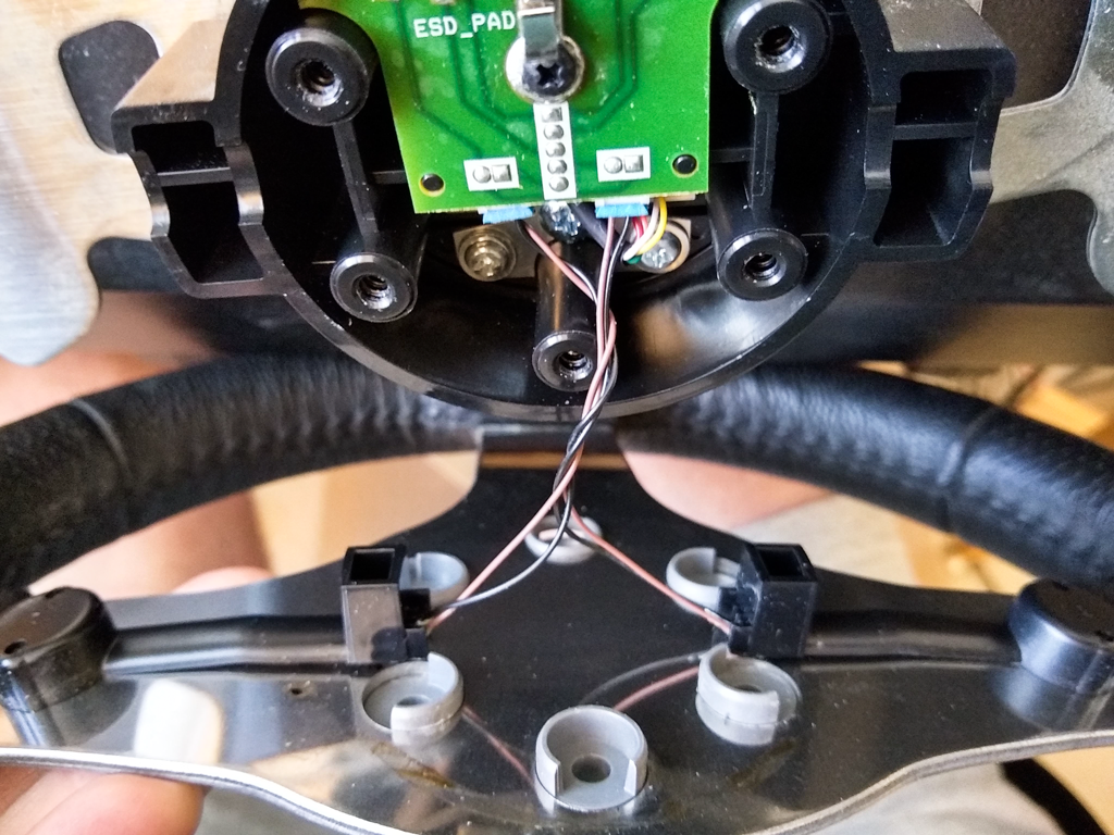
Wheel hub unmodified close-up
First thing to figure out is how to attach a plate to the wheel hub. There isn’t a heck of a lot of room and wanting to keep the original buttons, I had to accommodate them in the design.
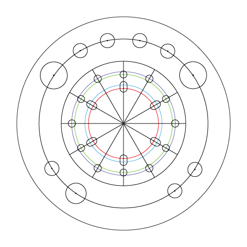
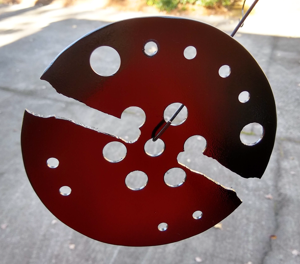
Modified wheel adapter template
Digging around on the web I located a template for a wheel adapter that allowed standard automotive steering wheels to be bolted onto a G25. I figured out what I wanted the maximum diameter to be and added that circle to the template. Then added a properly scaled photo of the actual wheel to another layer, added a center line for the buttons, and laid out the locations for nine push buttons and a rotary encoder.
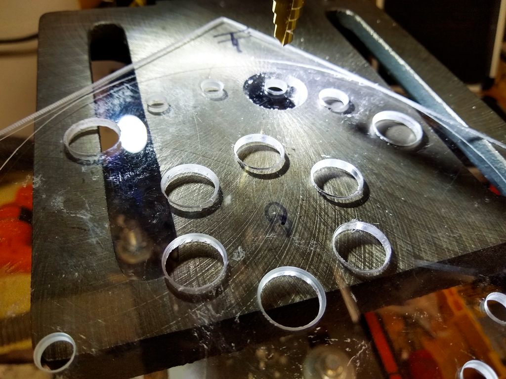
Then it was off to the shop, where I grabbed a scrap of sheet plastic, cut off a square on the band saw, and glued on a printed copy of the template.
Drilling holes for the switches
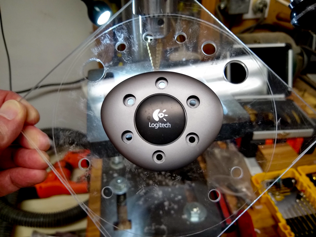
I used a step drill for all the holes, then checked the fit of the hub cover.
Center cover plate fits
Then things got a bit ugly.
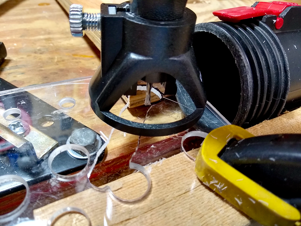
Routing a channel for existing switches
I needed space for the original switches and their wire covers. This would have looked a lot better if I’d taken the time to do a layout and cut it on the band saw, but I just threw a carbide routing bit into the Dremel and went at it. It’s all hidden behind the wheel where you have to look hard to see it’s a hack job. Good enough for me.
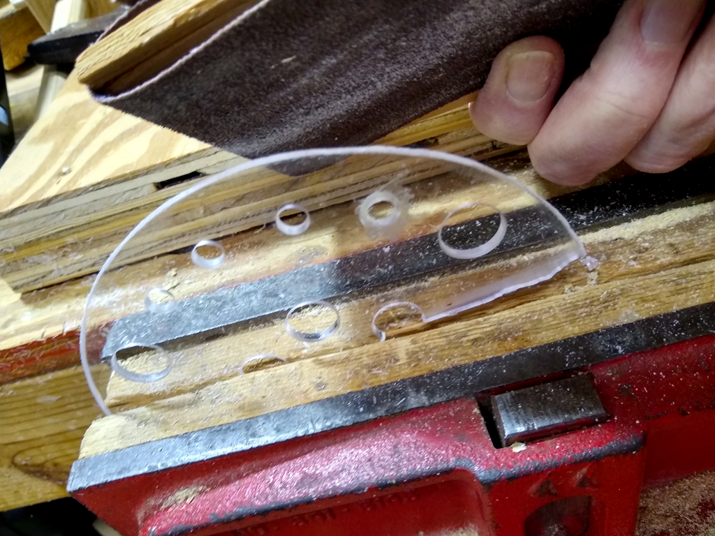
Sanding to the line
It was then rough cut on the band saw and sanded to the line I’d scribed with a compass earlier.
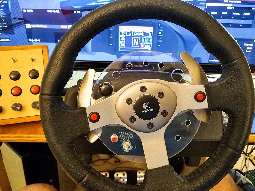
First test fit
Threw a couple switches on it and did a full test fit. Good enough to go to paint.
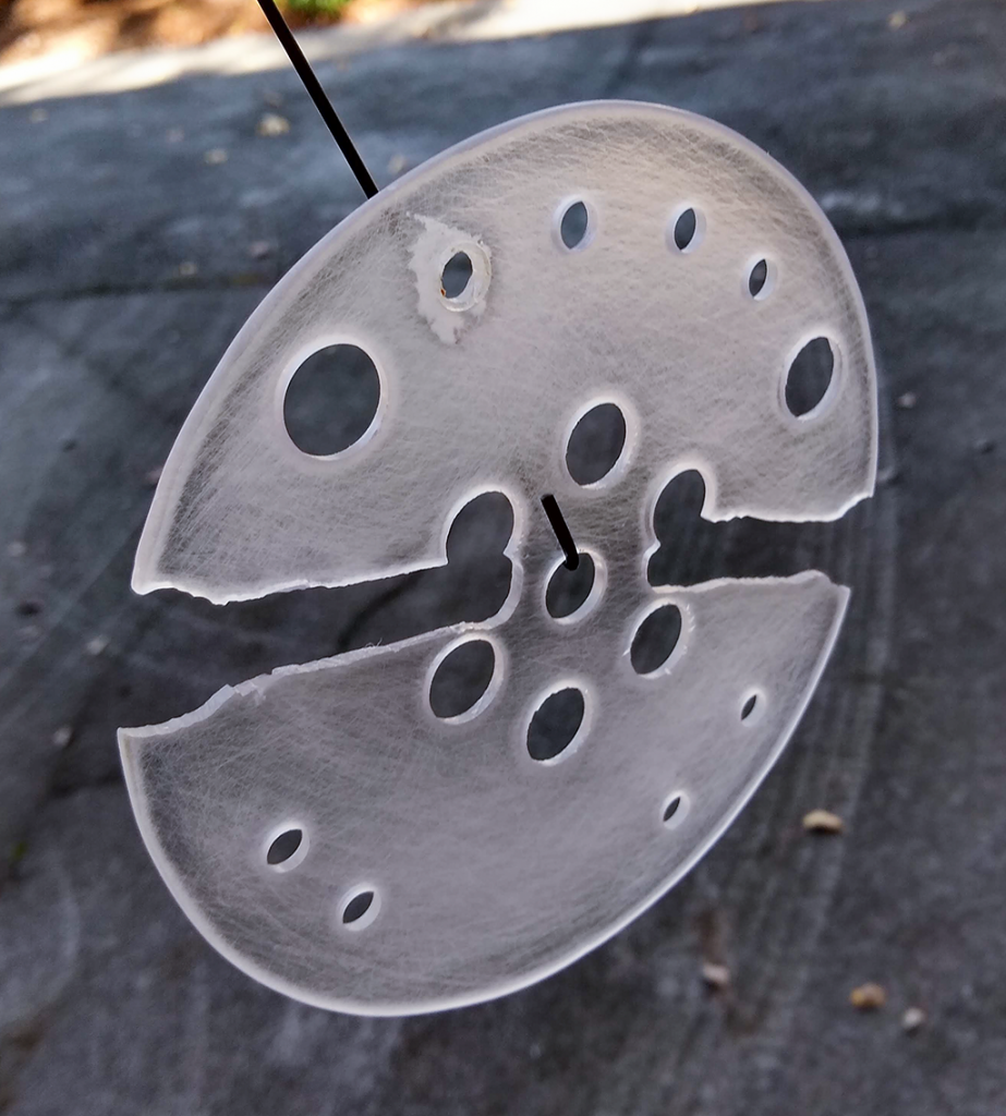
Prepped for paint
All sanded and ready to paint. No, it’s not perfectly round, but it’s close enough for me. And yes, that is a sloppy fill job where I’d gone one step too far on the bit on the first hole I drilled.
First coat
Applied light coats and managed to avoid any horrific runs in the paint. I went light enough you can still see some light through the first coat of flat black paint. The red is the light reflecting from my red t-shirt.
Interlude…
Right in the middle of the build, I was reminded why I’m doing this. Two laps from the end of a league race at Barber Motorsports Park, having chased down second place, running less than a second behind, I reached over to the button box to remove a tear-off so I could see, and hit the pit speed limiter instead. Took me a couple seconds to figure out what I’d done, and toggle it back off, but by then 2nd was long gone. Yeah, I’m really looking forward to having the controls I need during a race right under my fingertips instead of on the box on my left.
…back to the build.
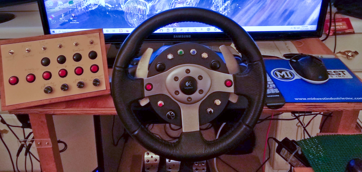
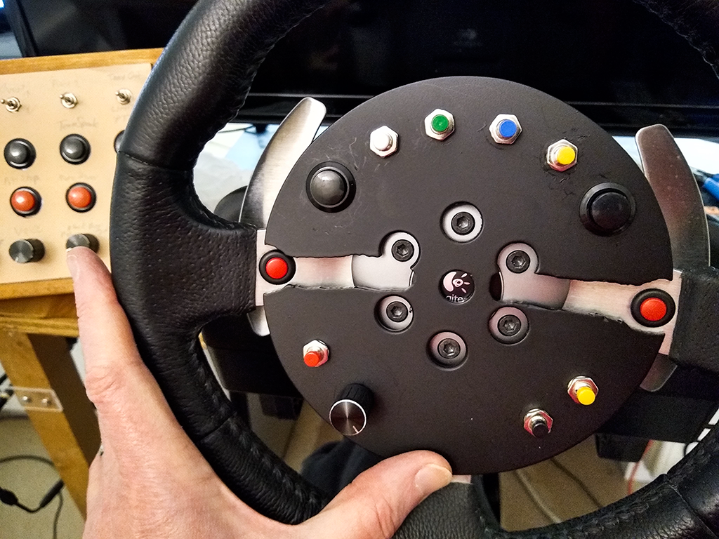
Painted with buttons
And it’s painted, with all the buttons and encoder installed. Looks a bit weird in front of the wheel, but I wanted to get an idea how it was going to look when completed.
I built this using PlatformIO IDE running on top of Microsoft’s Visual Studio. If you do any Arduino development using the Arduino IDE you really should check out PlatformIO – it is so much better.
#include <Arduino.h>
#include <Keypad.h>
#include <Encoder.h>
#include "Joystick.h"

//#define DEBUG
//#define TESTING

Joystick_ Joystick(JOYSTICK_DEFAULT_REPORT_ID,
  JOYSTICK_TYPE_GAMEPAD, 12, 0,
  false, false, false, false, false, false,
  false, false, false, false, false);
//Joystick_ Joystick();

const byte ROWS = 3; //four rows
const byte COLS = 3; //three columns
char keys[ROWS][COLS] = {
// original key map
//  {0,1,2},
//  {3,4,5},
//  {6,7,8}
// remapped to put keys in order I preferred
  {4,7,1},
  {5,6,2},
  {3,8,0}
};
byte rowPins[ROWS] = {4, 3, 2}; //connect to the row pinouts of the kpd
byte colPins[COLS] = {7, 6, 5}; //connect to the column pinouts of the kpd

Keypad kpd = Keypad( makeKeymap(keys), rowPins, colPins, ROWS, COLS );

Encoder myEnc(0, 1);
// encoder button & directions
const int encoderButton = 9;
const int counterClockwise = 10;
const int clockwise = 11;

const byte encSwitch = 9;
int lastButtonState = 0;
int buttonState = 0;
int debounceCount = 0;
const int buttonDebounce = 4;

#ifdef DEBUG
String msg;
#endif

long oldPosition  = -999;

void setup() {
    Serial.begin(115200);
    Joystick.begin();
    pinMode(encSwitch, INPUT);
    #ifdef DEBUG
    msg = "";
    #endif
}

void loop() {
    void joystickToggle(int button);

    // Fills kpd.key[ ] array with up-to 10 active keys.
    // Returns true if there are ANY active keys.
    if (kpd.getKeys())
    {
        for (int i=0; i<LIST_MAX; i++)   // Scan the whole key list.
        {
            if ( kpd.key[i].stateChanged )   // Only find keys that have changed state.
            {
                if (kpd.key[i].kstate == PRESSED) {
                    Joystick.pressButton((int) kpd.key[i].kchar);
                    #ifdef DEBUG
                        msg = " PRESSED.";
                    #endif
                } else if (kpd.key[i].kstate == RELEASED) {
                    Joystick.releaseButton((int) kpd.key[i].kchar);
                    #ifdef DEBUG
                        msg = " RELEASED.";
                    #endif
                }
#ifdef DEBUG
                Serial.print("Key ");
                Serial.print((int) kpd.key[i].kchar);
                Serial.println(msg);
#endif
            }
        }
    }

    // read rotary encoder
    long newPosition = myEnc.read();
    const int countDiv = 3;
    if (newPosition != oldPosition) {
        if (newPosition > (oldPosition + countDiv)) {
            joystickToggle(counterClockwise);
            oldPosition = newPosition;
            #ifdef DEBUG
            Serial.println(newPosition);
            #endif
        } else if (newPosition < (oldPosition - countDiv)) {
            joystickToggle(clockwise);
            oldPosition = newPosition;
            #ifdef DEBUG
            Serial.println(newPosition);
            #endif
        }
    }

    // read rotary encoder switch
    buttonState = digitalRead(encSwitch);
    if (buttonState != lastButtonState) {
        if (++debounceCount > buttonDebounce) {
            if (buttonState == 0) {
                Joystick.pressButton(encoderButton);
                Serial.println(" PRESSED.");
            } else {
                Joystick.releaseButton(encoderButton);
                Serial.println(" RELEASED.");
            }
            lastButtonState = buttonState;
            debounceCount = 0;
        }
    }
}  // End loop

#ifdef TESTING
const int delayTime = 200;      // slow it down so I can see it onscreen
#else
const int delayTime = 12;
#endif
void joystickToggle(int button) {
    Joystick.pressButton(button);       // button pressed
    delay(delayTime);
    Joystick.releaseButton(button);       // button released
}
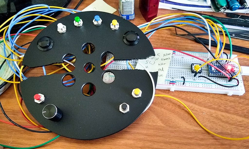
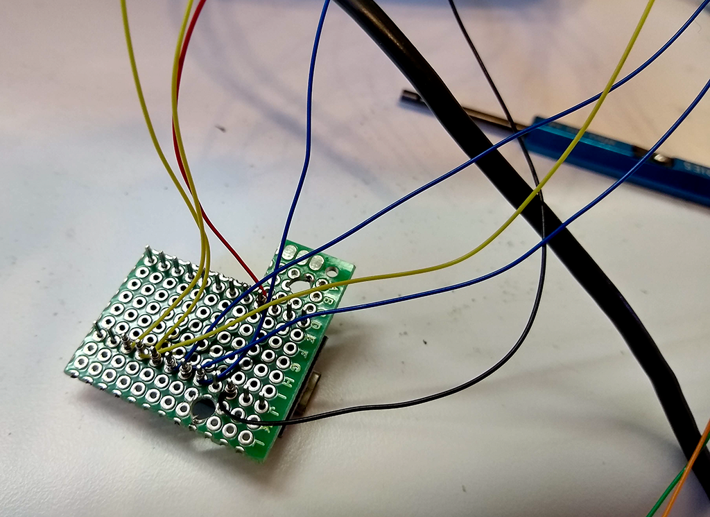
Wired it up on my desk for testing.
Breadboard setup for testing the code
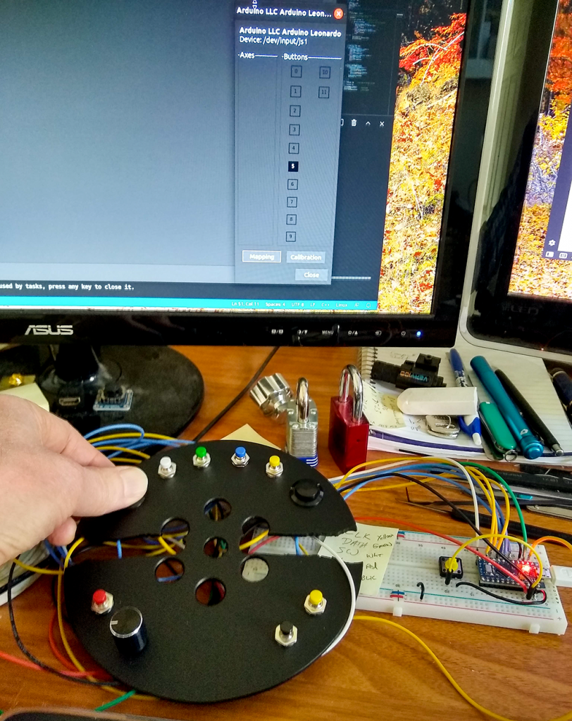
And, after fixing my stupid mistakes, it works!
And it’s working
Now the “fun” part – stuffing this all into the G25 wheel base. For some reason, the folks that designed the G25 did not put “make it easy to add additional hardware” very high on their list.
Dissecting the wheel base
Buried way down under all this is the opening through which the wires have to be run.
Wires run through hub (the first time)
Note the heat shrink I used for wire management the first time around. This will come back to haunt me.
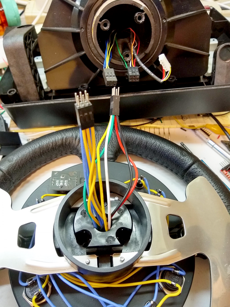
Dupont connectors used to allow wheel to be removed
I used 22 AWG stranded wire where it was exposed, but had to use 30 AWG wire wrapping wire to allow so many wires to fit through the opening in the base.
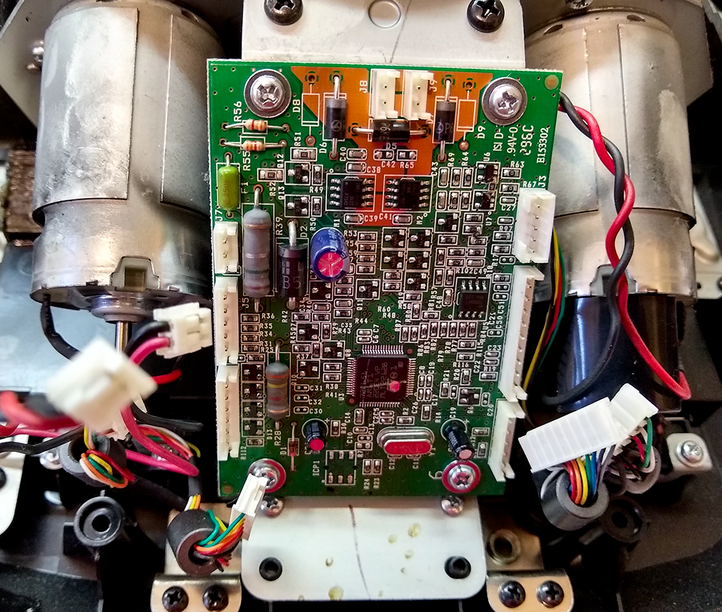
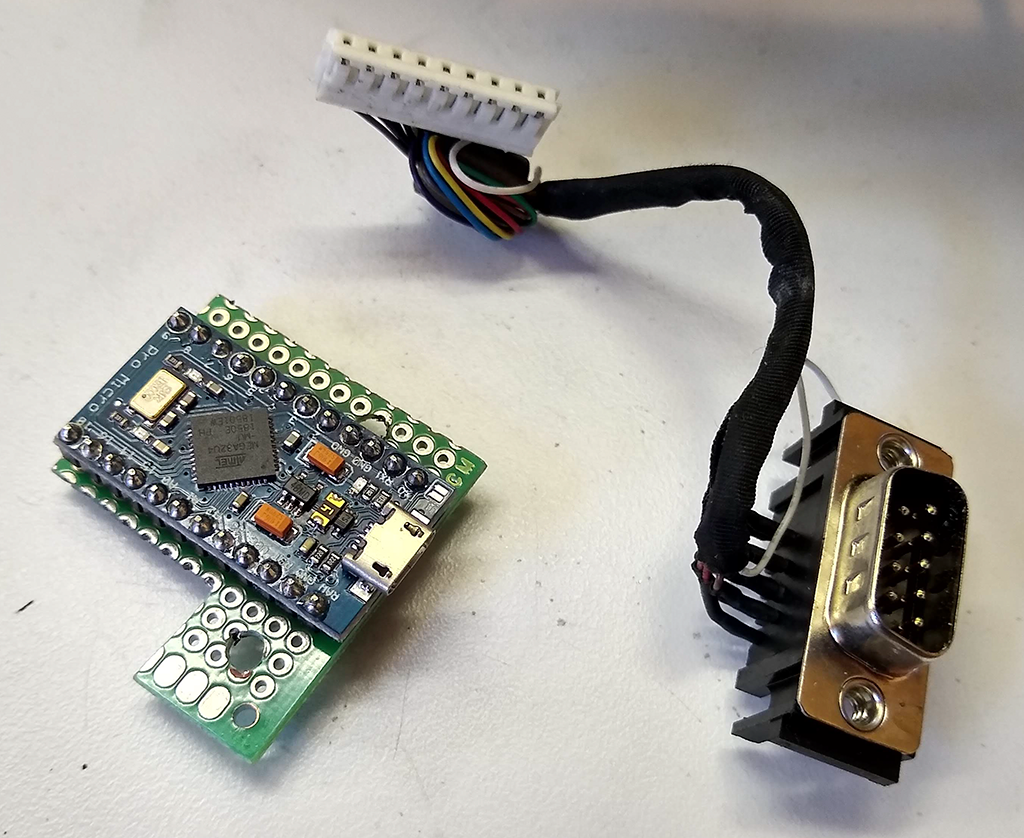
Arduino and connector for old shifter
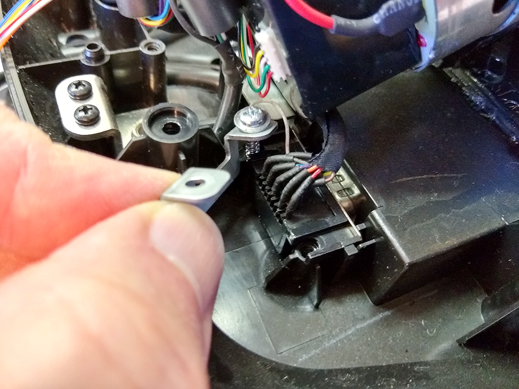
The original G25 shifter stopped working and was replaced a couple of years ago, so the location of the DB9 for the shifter seems like an excellent place to install the proto board mounted Arduino (used a generic HiLetGo branded Pro Micro – $5 each in lots of three on Amazon – even cheaper if you’re willing to order from China and wait).
Removing old DB9 connector
Pulled the old connector and cable.
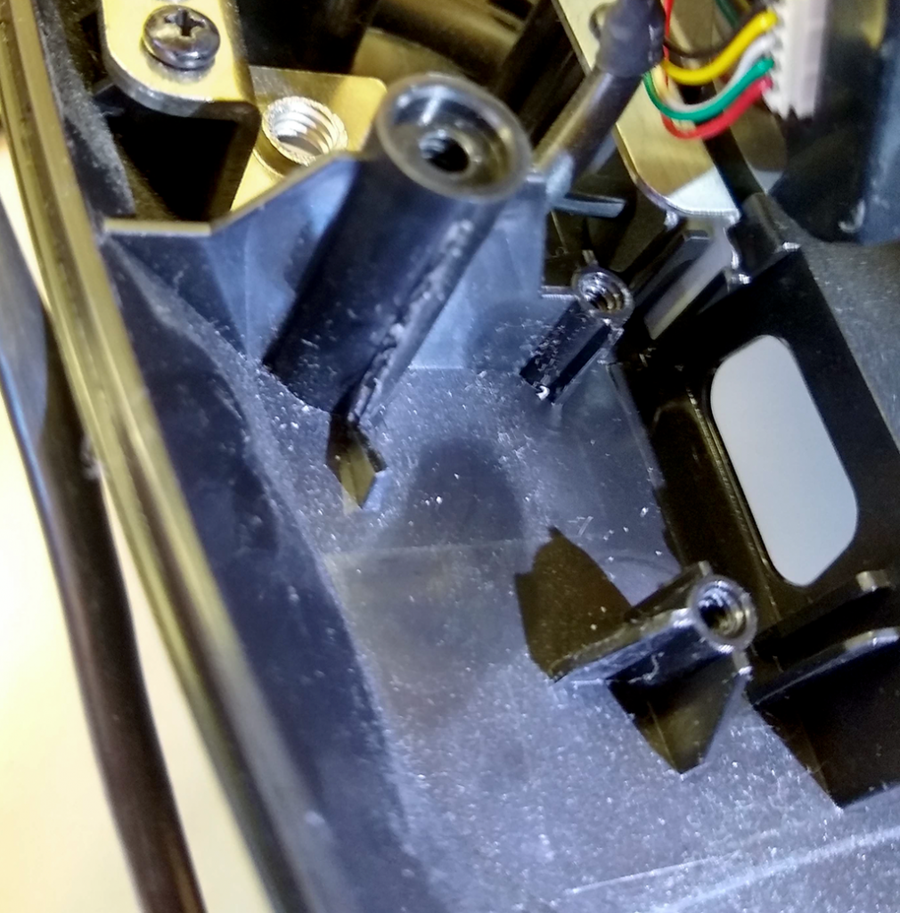
Modifying DB9 mount
Trimmed away some unneeded plastic to make some room.
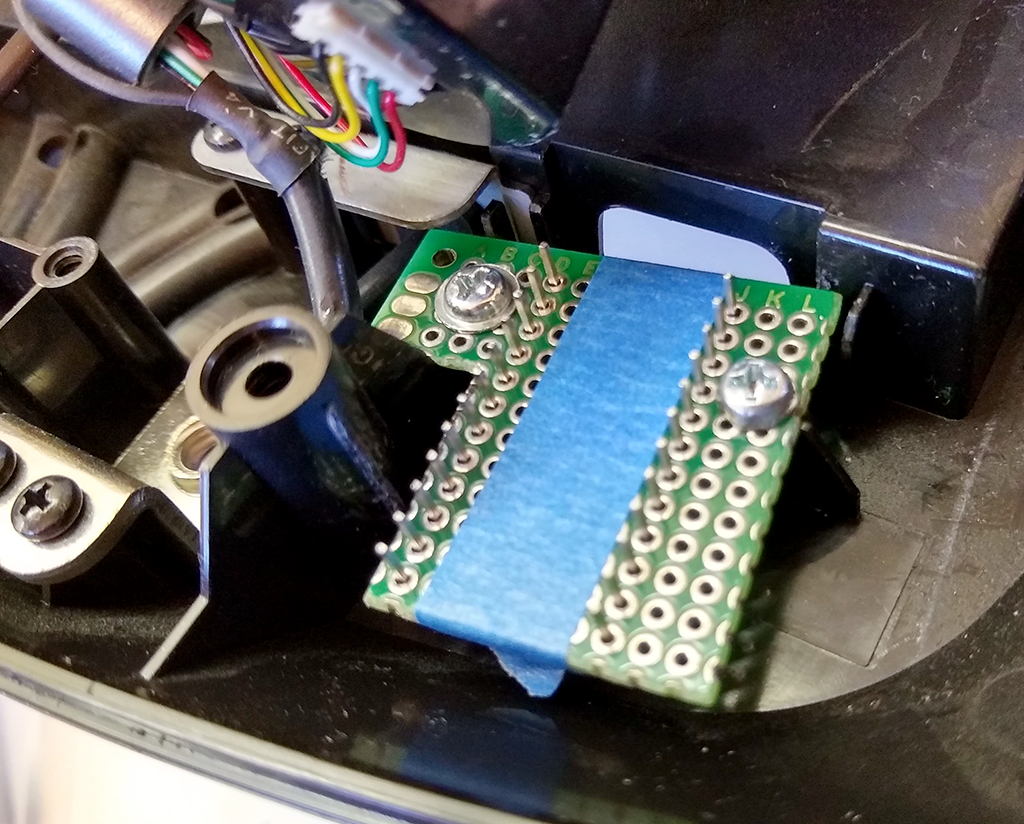
Arduino fitted
And the Arduino is fitted up and ready to be wired.
Wire wrapping Arduino
Then I wire wrapped all the switches to the Arduino and completely reassembled the wheel before starting final testing. Did you notice I said completely reassembled before testing? Three of the buttons registered as two simultaneous button presses on the computer. Pull out the DVM and sure enough, two of the six wires used for the keypad scanning are shorted together.
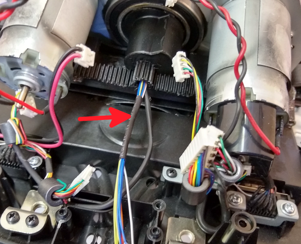
Completely disassemble the wheel again. This is not a five minute job… closer to half an hour, or more. Remember that red arrow? Seems I got a bit carried away shrinking that heat shrink tubing and melted the insulation on the wire wrapping wire. I forgot how much easier it was to melt than normal wire insulation.
Together again
Pulled all the wire wrapping wire out, de-wired the Arduino, and started all over again, from crimping on the Dupont connector pins all the way to rewiring the Arduino. Decided not to melt the insulation again, using small cable ties this time instead of the shrink wrap.
Used cable ties the second time around
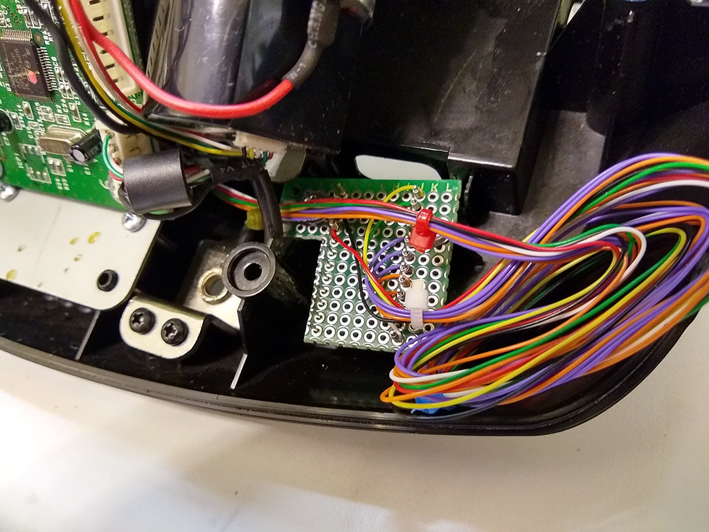
Yes, there is quite a bit of extra wirewrap wire. There are enough unused inputs on this Arduino to connect the pedals and hand brake, which are currently hooked up to another Arduino hanging off the side of the rig. Wirewarp wire is rather brittle and tends to break when you unwind it, so you need start with a freshly stripped bit every time. I’ve left enough here to allow the wires to be moved several times. The last thing I want to do is rip the wheel completely apart to run new wire.
The ugly, but functional, pedals and handbrake controller.
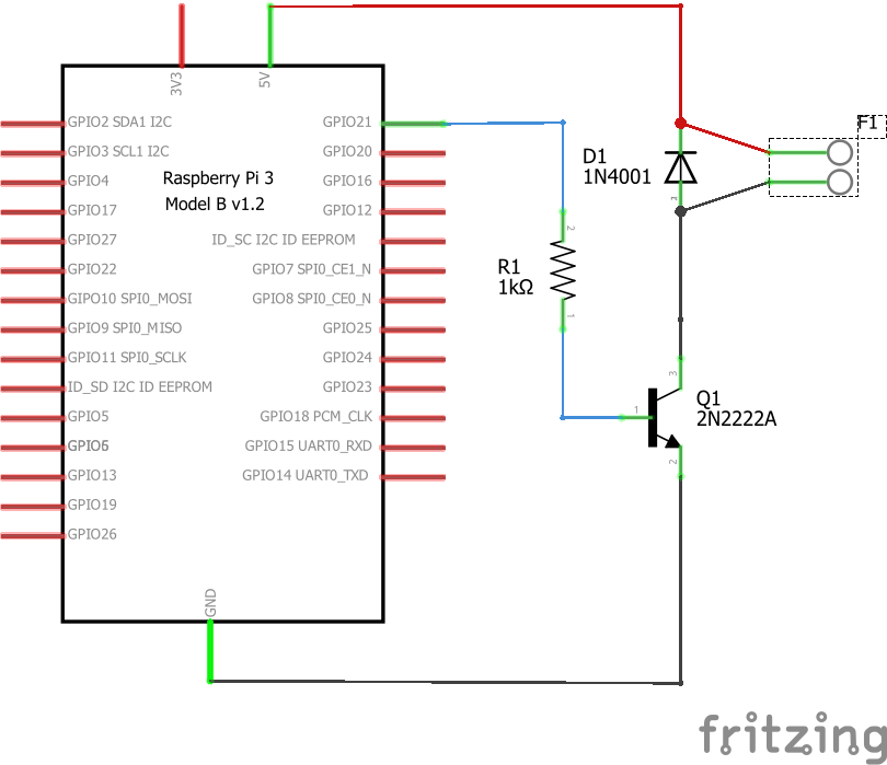
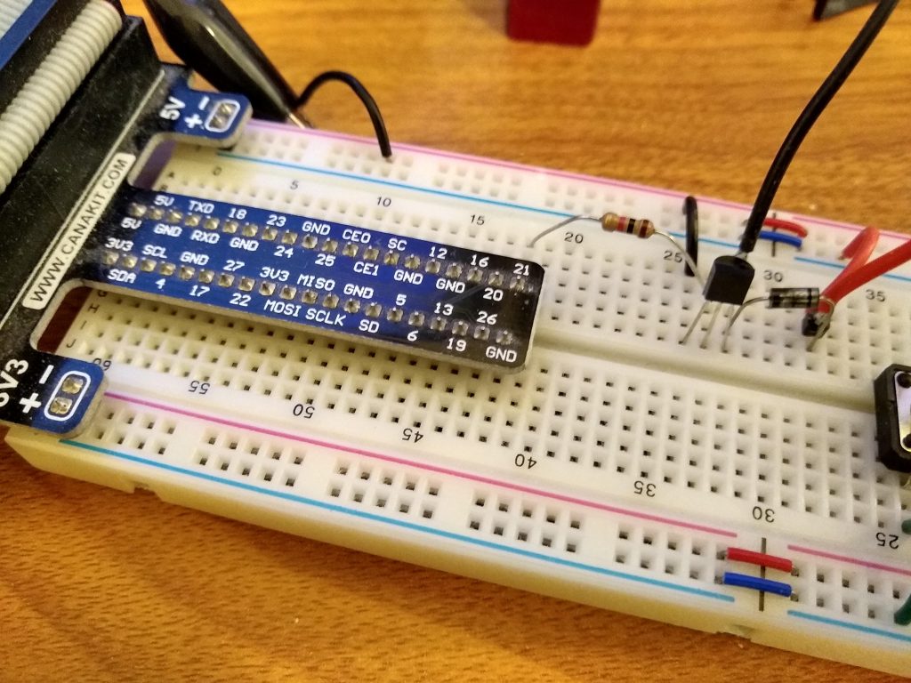
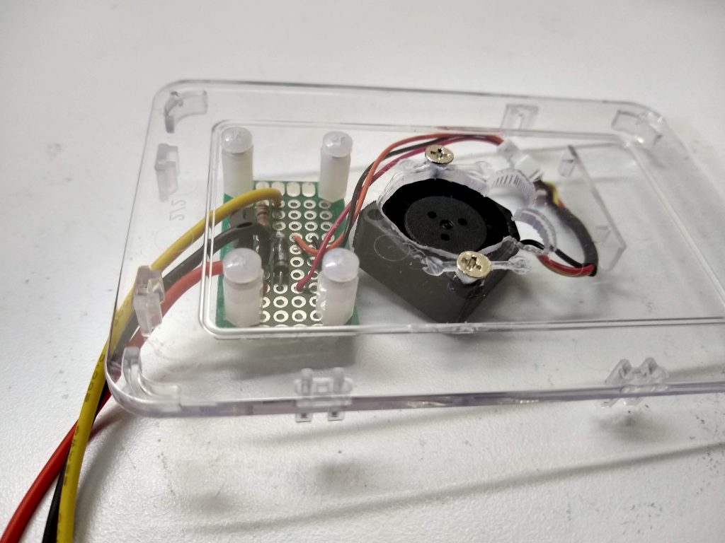
I have a Raspberry Pi 3 that takes care of some IOT odds and ends around here. The other day I noticed it was running a bit warmer than I’d like, so I threw together this quick hack using a 20 mm fan I’d parted out of an old junk laptop a while ago, a 2N2222 transistor, 1N4001 diode, and 1K resistor.
The circuit required looks like this (click on image to see instructables.com article).
First, I bread-boarded a circuit to drive the fan via one of the Pi’s PWM outputs. The Raspberry Pi PWM pins can’t source enough current to drive the fan (and the 3.3V output wouldn’t drive the 5V fan to full speed anyway), so I used a 2N2222 to control the 5V supply. A 10K resistor between the PWM output and the base, emitter to ground, and the collector connected to the fan. The other fan lead goes to the 5V supply. You need a diode across the motor so inductive voltage spikes don’t damage the transistor.
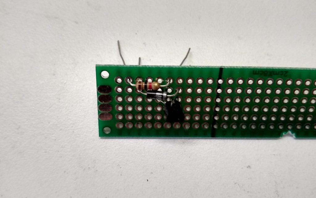
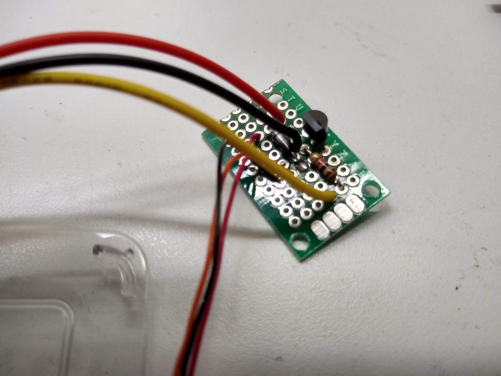
With that tested I fit the parts on a bit of protoboard.
Layout parts
Soldered parts, power, ground, PWM input, fan leads to the board.
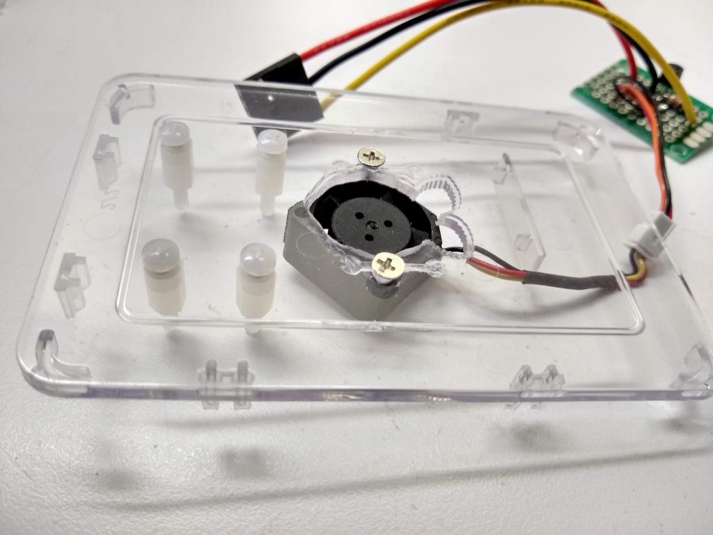
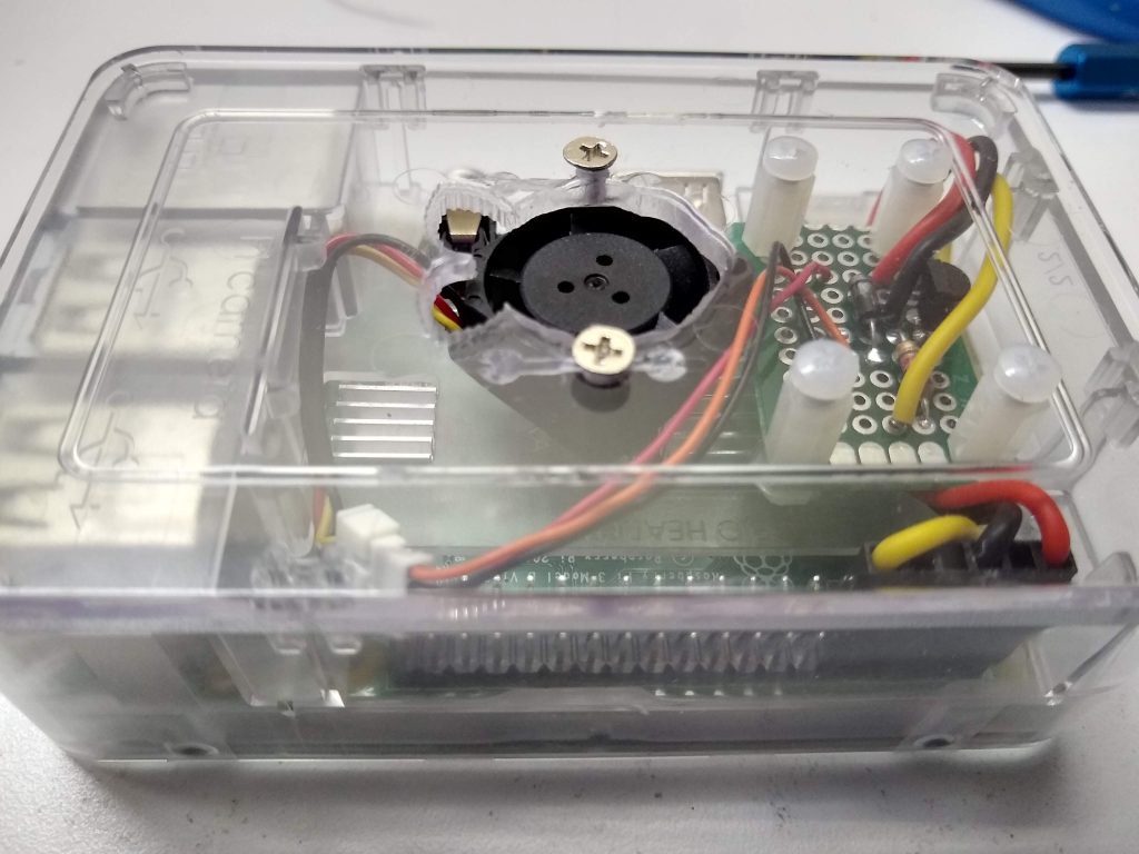
Then hacked a hole into the plastic case, mounted the fan, and installed standoffs to hold the board.
Next the protoboard was mounted to the standoffs.
Snapped on the cover and we’re ready to roll.
The code to drive it is fairly trivial. While the fan will run at 30%, it won’t start, so in the function that controls the fan I give it a short kick at 100% to get it going if it was previously off.
/*
Temperature controlled Raspberry Pi cpu fan via hardware PWM
Wiring diagram available here:
https://www.instructables.com/id/PWM-Regulated-Fan-Based-on-CPU-Temperature-for-Ras/
*/

#include <wiringPi.h>

#include <stdio.h>
#include <stdlib.h>
#include <unistd.h>
#include <stdbool.h>
#include <string.h>

const int PWM_pin = 1;   /* GPIO 1 as per WiringPi, GPIO18 as per BCM */
bool debug = false;

int main (int argc, char *argv[])
{
	FILE *tempFile;
	int temp;
	double T;
	void setFan(int);

	if ((argc == 2) && (strcmp("-d", argv[1]) == 0))
		debug = true;

	// can't do anything if setup fails
	if (wiringPiSetup () == -1) {
		fprintf(stderr, "wiringPi setup failed");
		exit (1) ;
	}

	// setup output
	pinMode (PWM_pin, PWM_OUTPUT) ; /* set PWM pin as output */

	while (1) {
		// get temperature
		tempFile = fopen("/sys/class/thermal/thermal_zone0/temp", "r");
		if (tempFile == NULL) {
			fprintf(stderr, "File open failed\n");
			exit(1);
		}

		fscanf(tempFile, "%lf", &T);
		T /= 1000;
		if (debug)
			printf("CPU temperature is %6.3f C\n", T);
		fclose(tempFile);
		temp = (int) T;		// don't care about details, so just truncate it

		setFan(temp);
		sleep(10);
	}

	exit(0);
}

// set fan speed based on CPU temperature
void setFan(int temp) {
	long map(long, long, long, long, long);
	int speed;
	static int last_speed = 0;

	if (temp < 50)			// under 50C don't run fan
		speed = 0;
	else if (temp > 80)		// anything over 80 run 100%
		speed = 100;
	else {					// vary speed as temp increases
		speed = map(temp, 50, 80, 30, 100);
	}

	if (speed != last_speed) {
		if (debug)
			printf("Setting fan to %d\n", speed);

		if (last_speed == 0) {
			pwmWrite(PWM_pin, 100);		// give it a kick start
			delay(100);					// let fan start
		}
		pwmWrite(PWM_pin, speed);
		last_speed = speed;
	}
}

long map(long x, long in_min, long in_max, long out_min, long out_max)
{
	return (x - in_min) * (out_max - out_min) / (in_max - in_min) + out_min;
}
I installed the compiled program in /usr/local/bin and added a line in rc.local to run it when the Raspberry Pi boots. Where I’ve set the temperature threshold, the fan kicks on occasionally while the Pi is idle. As soon as any sort of load is added, the fan starts almost immediately and speeds until the temperature levels off. The fan provides more air than is actually needed to keep the Pi cool, as even under full load the fan doesn’t come up to full speed.
I’ve run into several situations where a marking gauge would have come in really handy. After I saw Rex Krueger’s video last June I kept telling myself I should just make one. Well, I finally got a round-tuit.
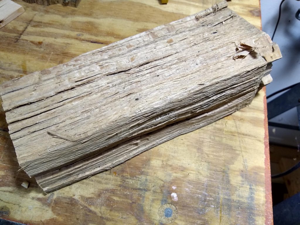
I didn’t have any hardwood lying around that was thick enough, so I pulled a piece of oak off the wood pile.
After I planed a section flat on one side, I cross cut the end square, and marked out where to make the rip cuts.
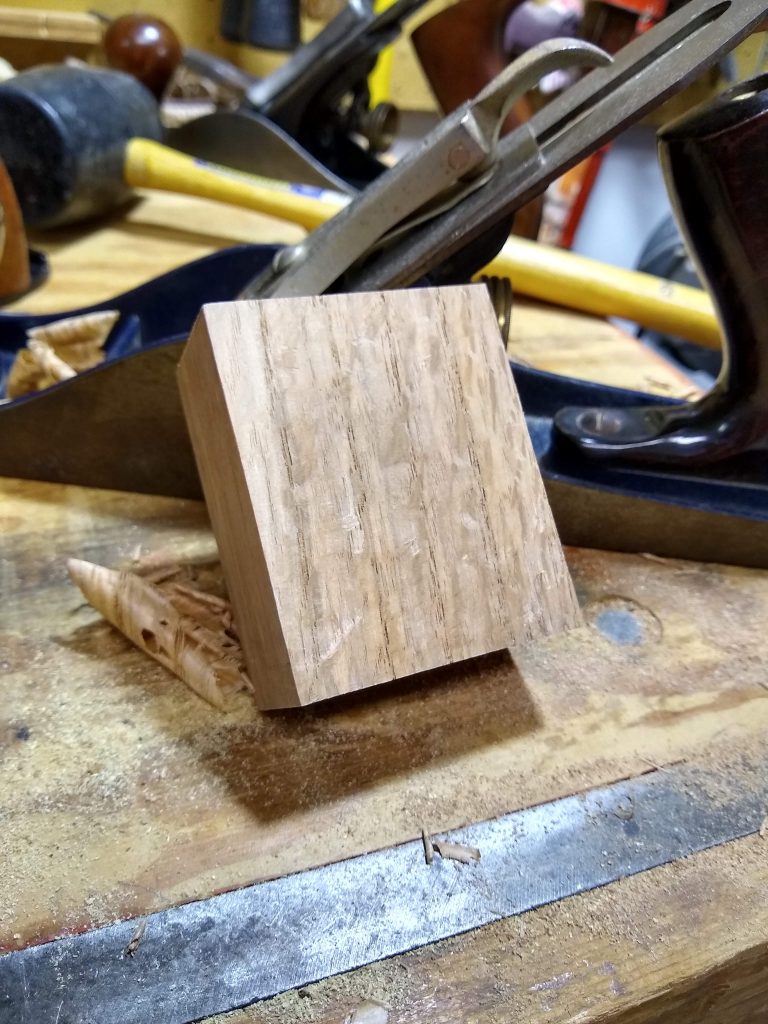
I made the three rip cuts, then cross cut the piece off the end of the log to end up with a roughly 2 3/4 x 2 1/4 x 1 1/4 piece of quarter sawn oak which I proceeded to plane square on all six sides. This is the fence.
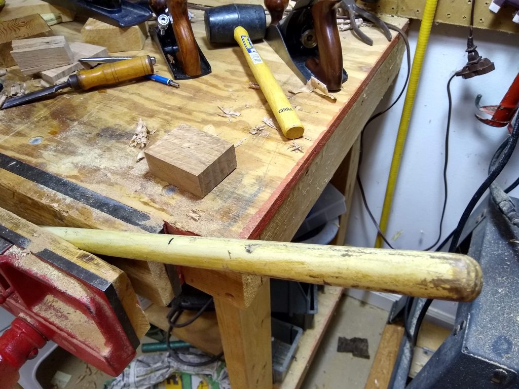
I didn’t have any large dowels, but I did have an old worn out broom with a handle a bit over 7/8″ in diameter. I still have an old worn out broom, but it’s handle is 8″ shorter than it used to be.
I had some 3/8″ dowel on hand and cut off a 3″ piece for the locking pin.
First I planed a flat on one side of the broom handle, then slowly rotated it while planing a little off each time until it would fit into a 7/8″ hole.
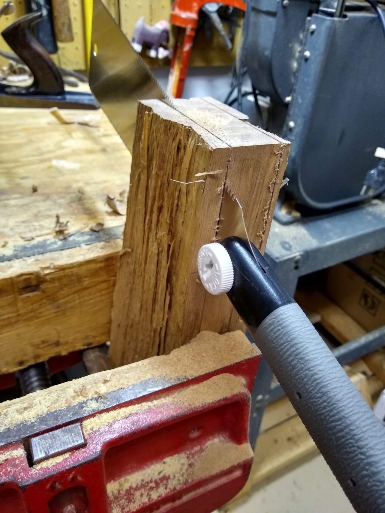
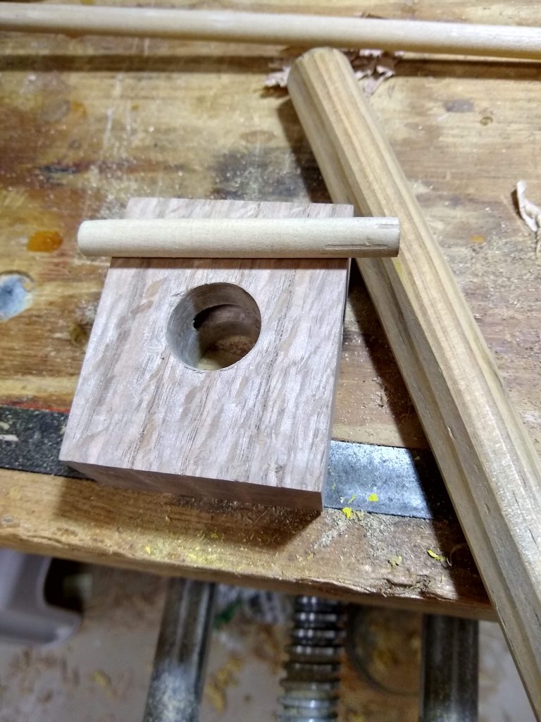
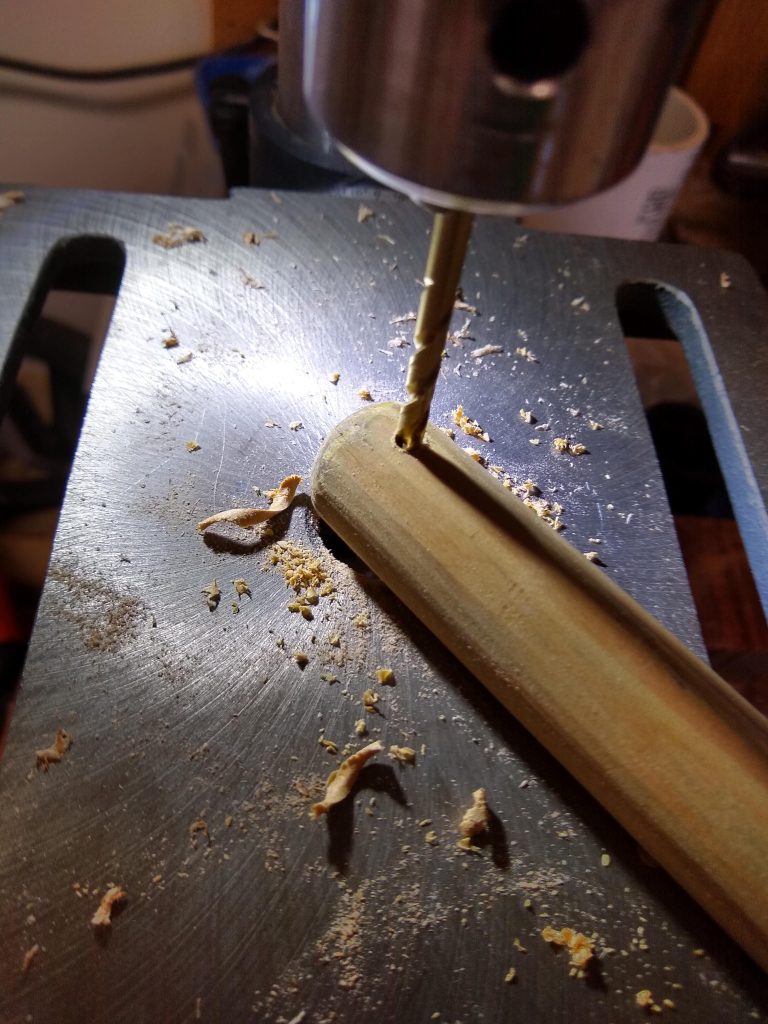
I then drilled 3/8″ and 7/8″ holes such that the 3/8″ hole intersected one edge of the 7/8″ hole.
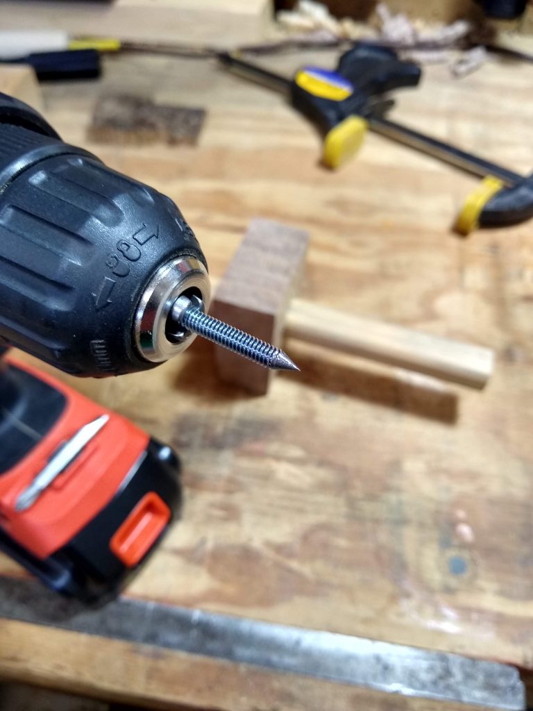
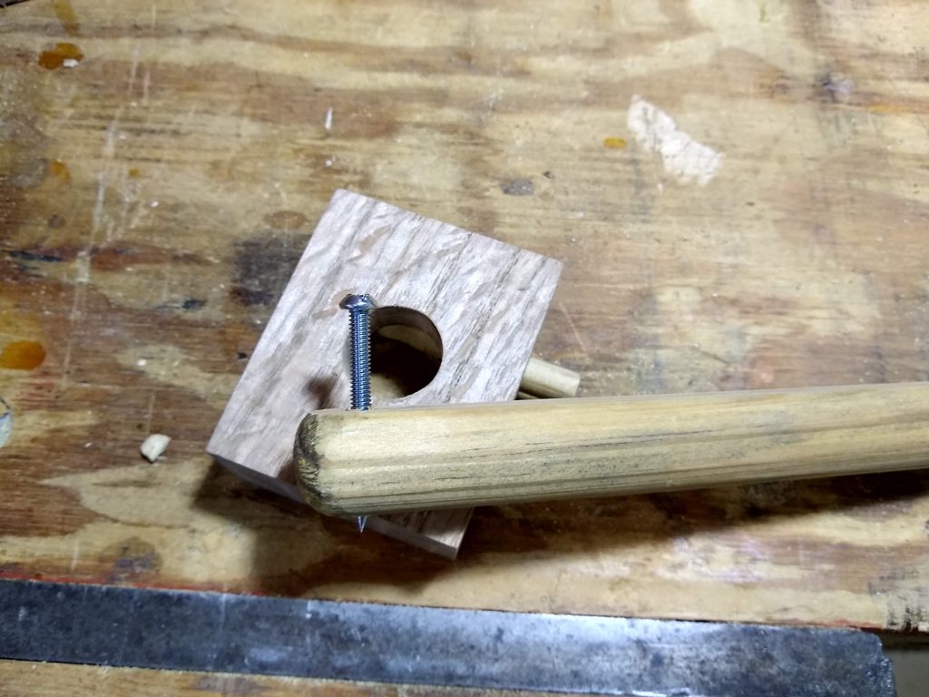
I have a bin full of these small machine screws, so I chucked one up in the drill and spun it against the grinder to form a point.
Then drilled an appropriately sized hole in the piece of broomstick,
and threaded in the machine screw. Easy to adjust the length. Easy to swap out of I decide I’d rather use one ground to a knife edge instead of a point.
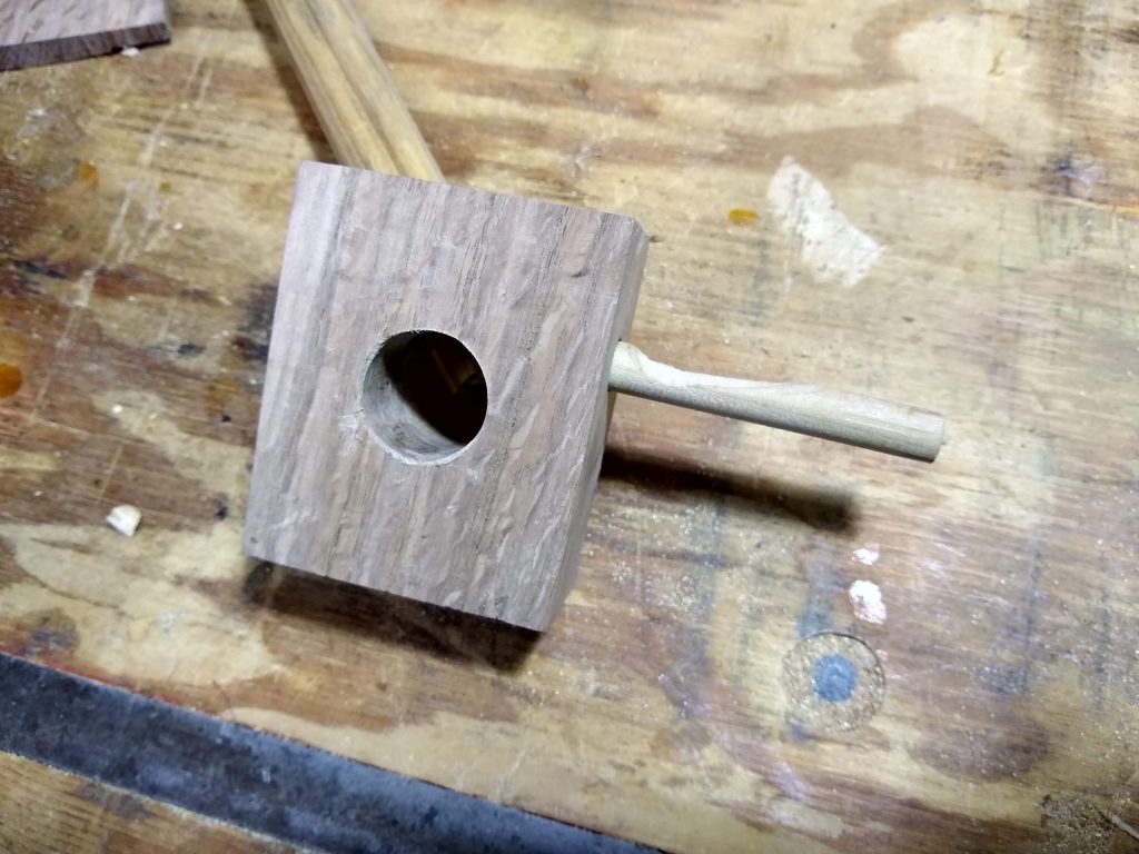
I messed up a bit on the locking pin. The bottom of the cutout should be flat, just clearing the flat on the bar. I went too deep, didn’t get it flat, and the bar rotates slightly before locking. An easy fix – I have several more feet of 3/8″ dowel. Making another one that’s right will take about ten minutes.
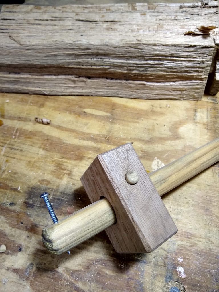
I then chamfered all the edges to make it comfortable to hold.
The final product works great, and being made from scraps, cost absolutely nothing. You can operate it with one hand. To lock it really tightly just give the pin a light tap on the bench. Another light tap on the other side unlocks it.