Scrubbing a Windsor Plane

So, I picked up an old #4 Stanley on Ebay for $40 intending to set it up as a scrub plane, but ran into a problem. Rather than being an old junker, aside from the iron suffering some abuse, the plane was in absolutely perfect condition. Then I made the mistake of putting an edge on the iron (had to grind off almost 1/8″ to get rid of the dings and chips) and trying it… I love this plane. No way I’m hacking it up to make a scrub plane.

Back to the drawing board. I’d seen a Stumpy Nubs video years ago where he’d used a Harbor Freight No. 33 Windsor to make a scrub plane, so, $12 (with coupon) later I’m the proud owner of an absolute piece of junk “smoothing” plane.

You know those pretty photos you see on the HF website? Well, this is what you actually get.

If they’d cut the arc in the iron the other way around it’d have saved me some time, but after some work on the grinder, an old, beat up, very not flat oil stone, some sandpaper and leather strop, I’ve got the iron set up with a 3″ radius arc and decent edge. A bit of file work to open up the mouth a bit, and I’ve got a scrub plane that rips through rough wood just fine.
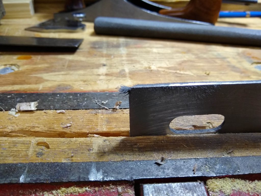
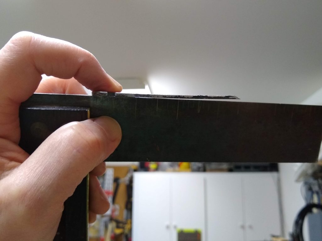
The sides of the iron were so nasty I took a file to them in self defense. Out of the box, they were sharper than the edge.
<sarcasm>Nice, flat iron, right from the factory.</sarcasm>

Yeah, it’s a piece of junk, but you can turn this $12 turd into a very decent scrub plane.

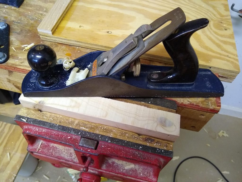
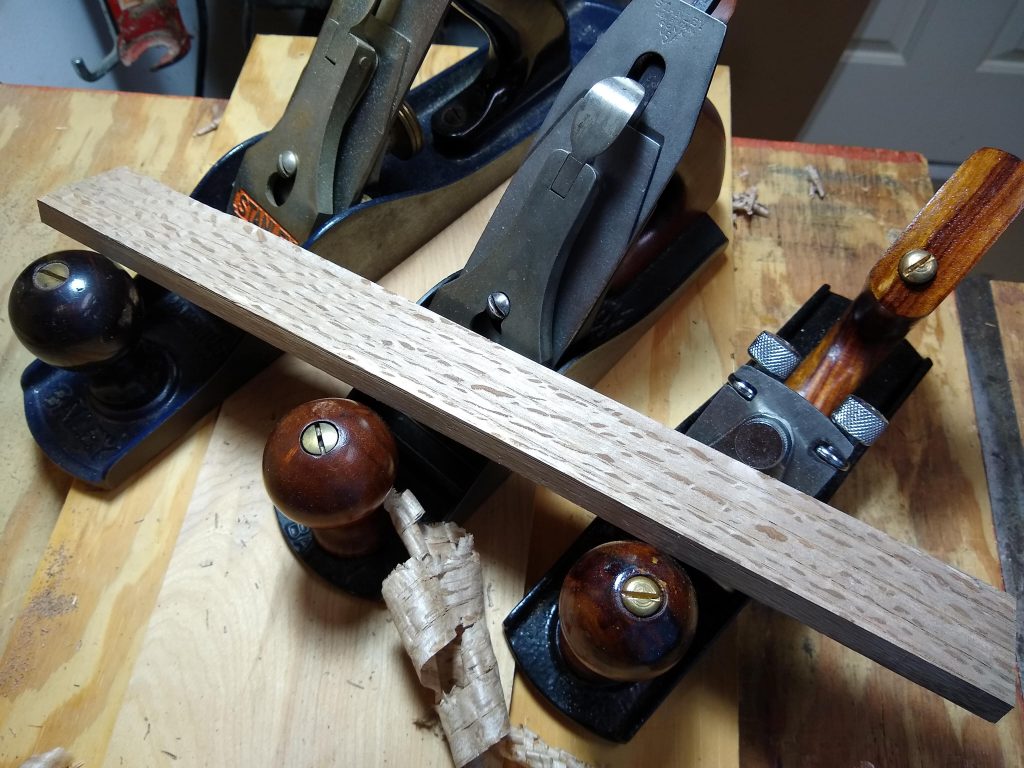
I split this off a piece of firewood and squared it up in a few minutes with my new scrub plane. Just a few passes with the #5 to flatten it and I’ve got something ready to use.
33 Button Box with Rotary Encoders

Controlling your car in a sim using the keyboard isn’t ideal. Too many keys you don’t need placed to closely together to operate by feel. Taking your eyes off the road long enough to find and press the right key often results in unwanted off-road excursions. A button box with which control all the things that need changing during a race is a much better solution.

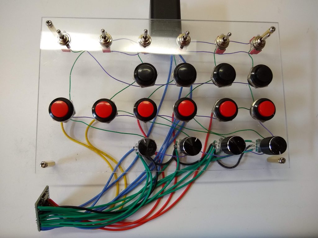
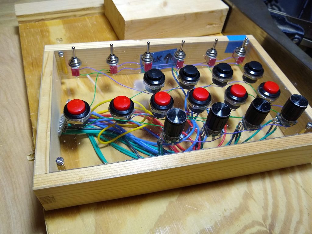
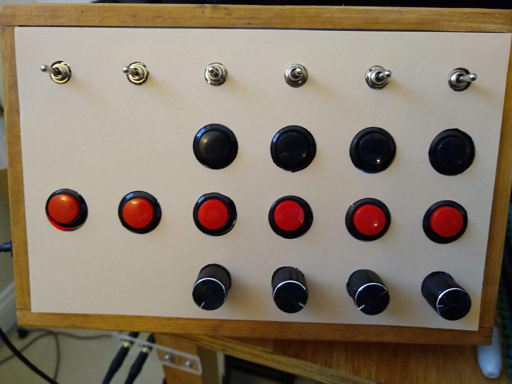
So, I’ve been looking at amstudio’s sim racing button box for over a year, but just got a’round tuit. Didn’t buy a box. Front panel is leftover acrylic sheet I had lying around the shop. This thing ain’t gonna be pretty, but it’ll work.

Probably should have painted it before installing the switches.

This is actually a complete rewire after I’d totally botched it the first time. I messed up the grid, and after trying to fix it three or four times, just ripped it all out, figured out the correct layout on paper, and did it right.

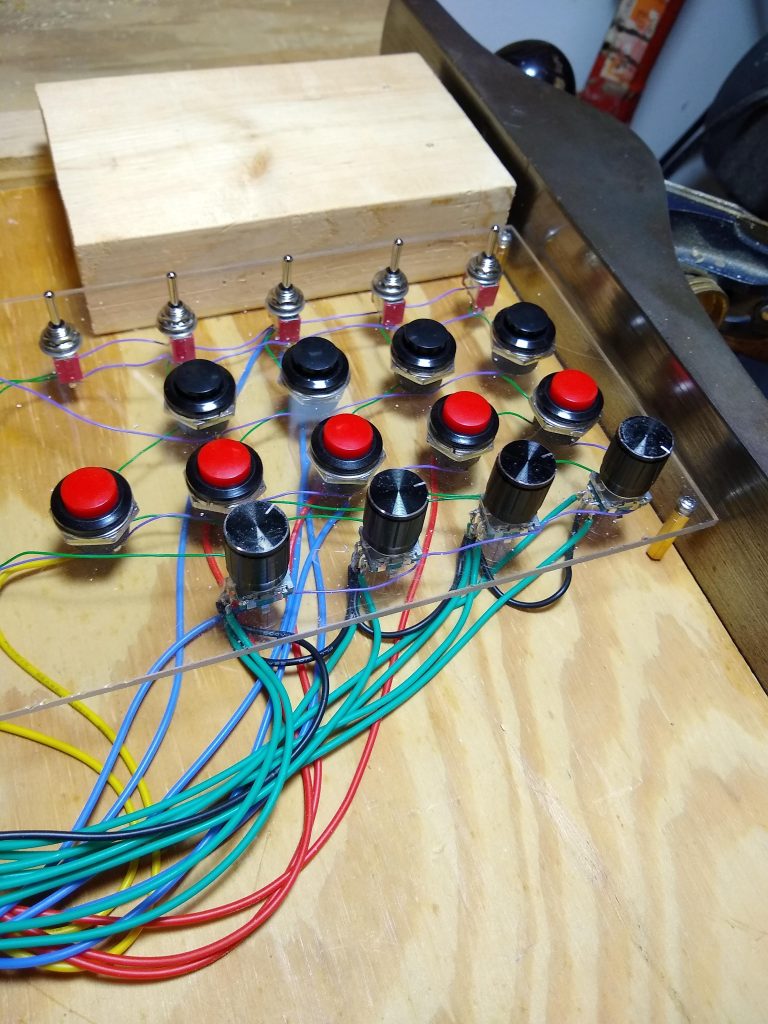
I suppose I could have painted the panel but I plan on using more than one layout and decided to just slap a overlays on it.

Sliced up a 2×4 to make the sides of the box.

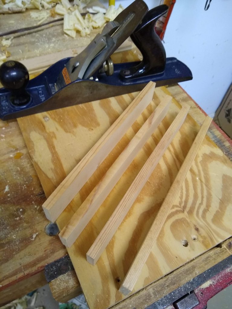
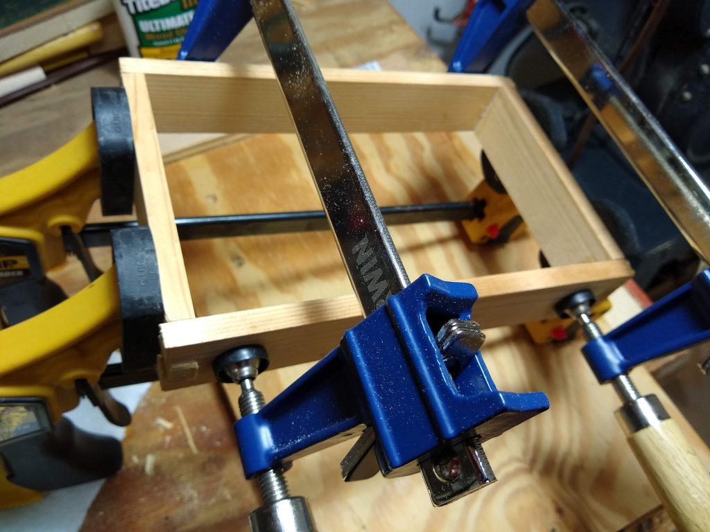
Continuing the “use junk already in the shop” theme, I re-sawed a piece of 2×4 to create the sides of the box. Planed them smooth, cut bridle joints, then assembled and glued the frame.

Smooth and planed to uniform thickness.
The glue up.
Turns out the front panel was slightly out of square. Shooting board took care of that.

I did have to tweak the panel a tiny bit as the frame was perfectly square, but the panel was off by a few thou. Then added some blocking to support and mount the panel.

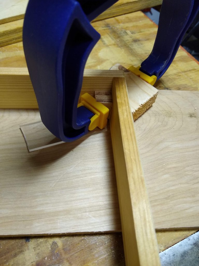
Glued in some corner blocks for mounting the panel.
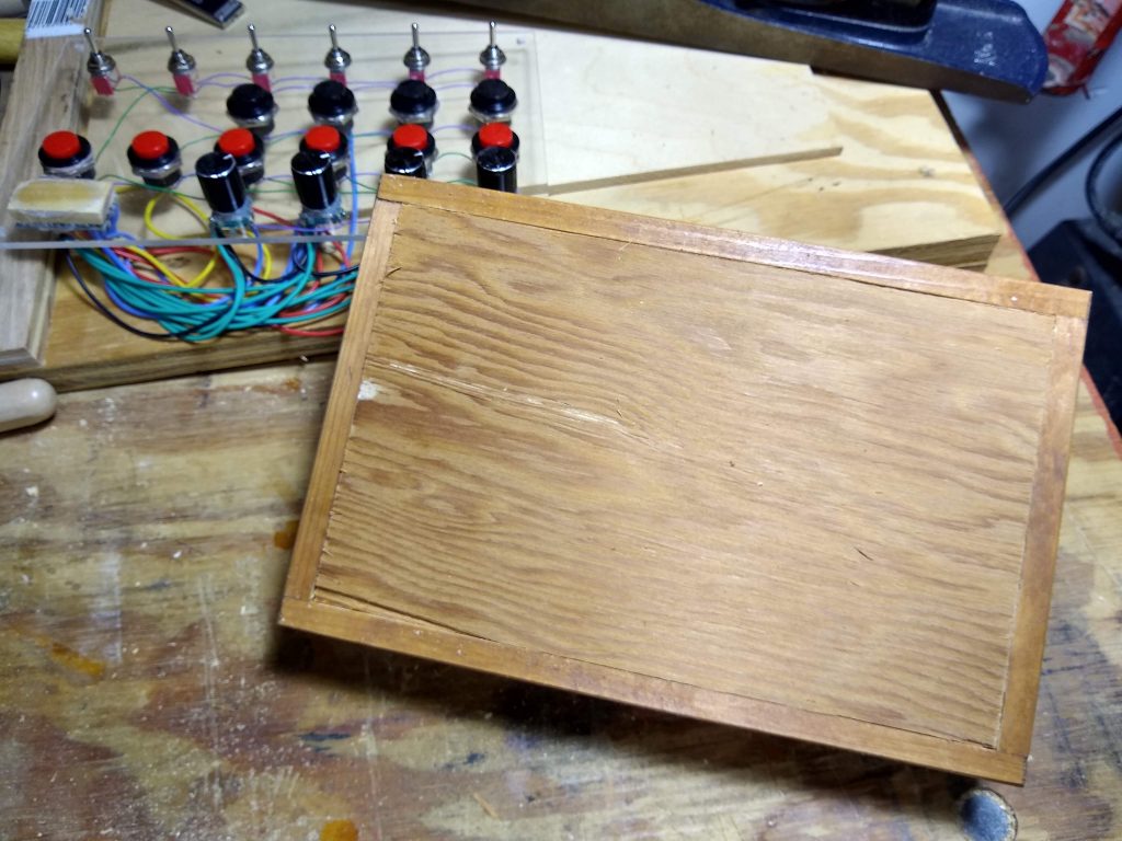
Added blocks in the middle to stop the panel flexing, then cut and glued in a piece of scrap 1/4″ plywood for the back.
Might not be pretty, but it works just fine.

I have a few small bits of 1/4″ plywood in the scrap bin, so that’s what I used for the back and part of the stand. The stand uprights were made from the pine cutoffs from the foot stool I made for my wife a while ago.

Screwed together a bracket and screwed into the “cockpit”.
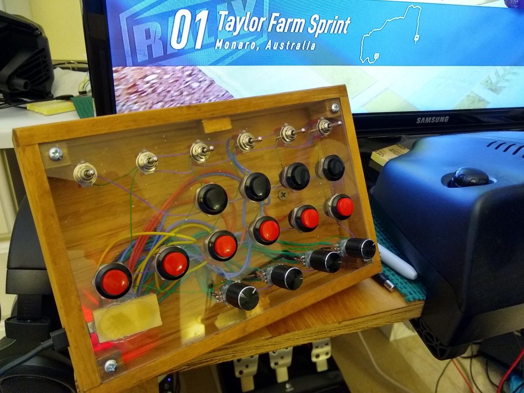
And it works just fine.

And there you go. Installed and working. The overlays seem to stay on just fine by laying them over the switches. These are card stock. When I finalize the layouts I may go with something heavier and some Velcro to keep it in place.

Used the Illustrator panel layout to create a template for holes for all the switches.

It’s a bit of a PITA to cut out the overlays with an X-Acto knife, but I only use a couple different switch layouts. I’ll eventually print up a nice one once I’m happy with the switch layout and retire the hand written in pencil layouts I’m currently using.

Check out amstudio’s video for a the software for the Arduino. All I’ve changed are the limits to include one more switch.

CrashPlan Still Sucks

Backup software that tells you it’s backing up your stuff when it isn’t SUCKS.

Seems CrashPlan still hasn’t fixed the wonderful feature I ran into a couple years ago where you hit a magic limit and your backups stop working…. while their software continues to send you weekly emails telling you that your stuff is all backed up.

It makes perfect sense that they need to use resources (RAM) to keep track of whether or not a file that’s being tracked has changed. If you have a large number of files, that can mean a LARGE amount of resources.

Their software has a default limit on the amount of RAM it will use to track changed files. No problem with that.

When their software hits that limit, and cannot allocate the memory it needs, it crashes, writes a restart.yyyy-mm-dd_hh.mm.ss.log file in the folder where the binary is installed. Then it restarts… without telling you it’s crashed. I DO have a problem with that.

In fact, this morning, when I needed to restore something, I discovered that I have a problem with another machine that hit that limit a few months ago. No, the most recent version of CrashPlan does NOT detect that this has happened. I’d complain and ask that they do this again, but they obviously don’t care enough about the issue to have done anything about it.

Other than that problem I like using CrashPlan, so I’ve written some scripts that run weekly that let me know if this has happened. I suggested that they needed to do this, but, at least in the most recent version I’m aware of, they have not done anything to address the problem.

Sim Racing E-Brake Rev. 1.0

I’ve been driving Dirt 2.0 a lot lately and decided using a button for the hand brake wasn’t ideal. It was time for an analog hand brake. Club Sport makes a really nice one for $120 plus shipping and handling.

Not. Gonna. Happen. I’m too cheap to spend that for something that simple. Time to roll my own.

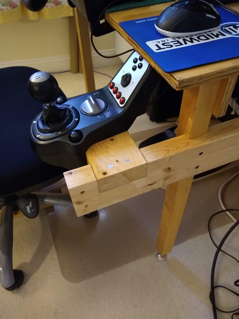
A nice, home-made kludge would look right at home installed on my crude racing rig… except there’s a mouse platform in the way.

But that’s not really much of an obstacle when everything is made of wood. Ready to start prototyping.

So, where exactly do I want it? Nothing I tried was quite right because I was stuck placing it just a little too far to the right, but this was as good as I could get.

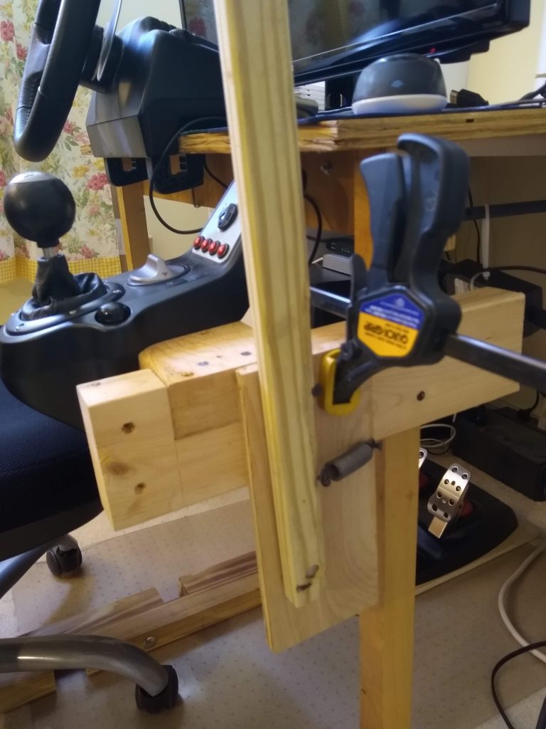
It needs to pivot and return when released. Check.

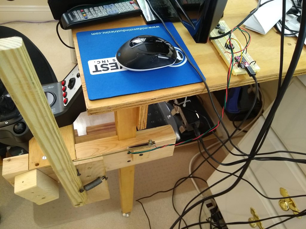
It needs to connect to a linear potentiometer. Added high tech coat hanger push rod. Check.

It needs a stop so I don’t break the potentiometer by pulling too far. Check.

With the mechanics all working, I wired the pot to an Arduino Pro Micro installed in a solderless prototype board – this was super complicated, all three wires. 5V, ground, and A0 input. Loaded the sketch amstudio used for his handbrake (YouTube https://youtu.be/kv0FTpRLFMY) off github (https://github.com/AM-STUDIO/Analog-E-Brake), et voilĂ , I have a working hand brake.

Total cost? $12.50. The 10K slide pot was $5.50 and the Arduino Pro Micro $7. Everything else was scrap that was lying around the shop. Well, I had spare Arduinos lying around from another project – they’re so cheap it doesn’t make sense not to order several at a time, so the only thing ordered specifically for this build was the $5.50 10K pot.

Eventually, I’ll build one that’s an enclosed unit, but for now this will do. It could also use a stronger spring and better stops, but it works great.

Plane Iron Killer

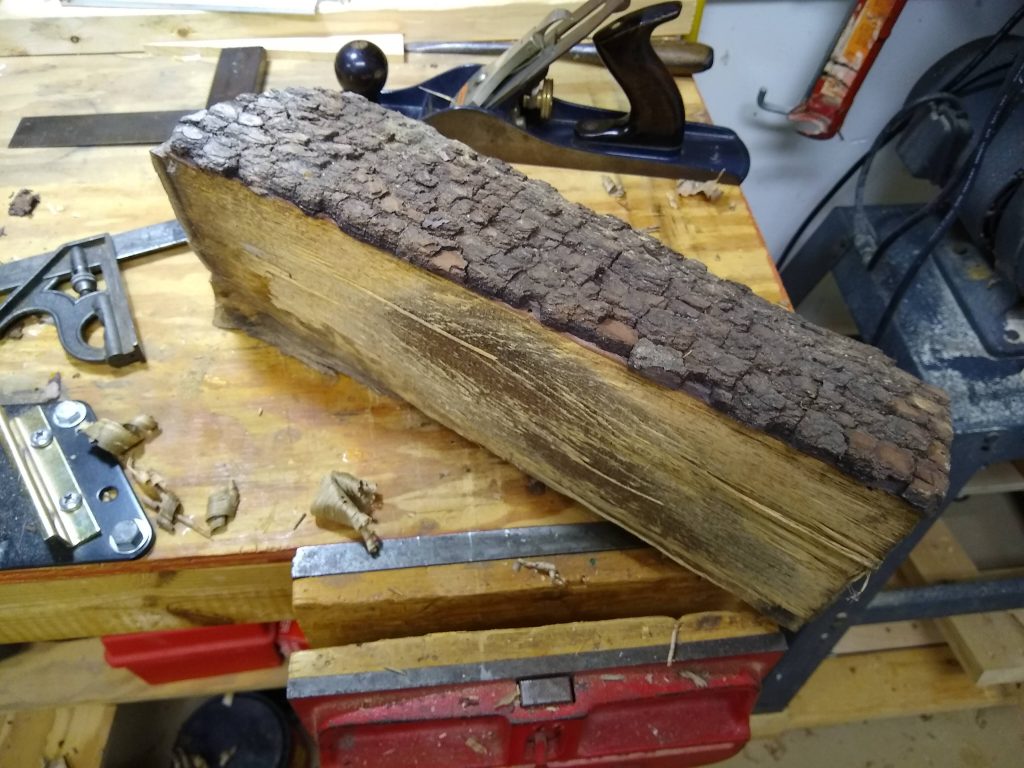
I just got a ’round-tuit’ and started processing a few pieces of Persimmon my step-son gave me a couple years ago. Not sure what it’s gonna be, but it ain’t gonna be nothing while it’s just split firewood

Planing this stuff is like planing rock… I’ve never had anything kill the edge on the plane iron this fast. I’m sure it doesn’t help that the outer layer had dirt embedded in it that wouldn’t scrape off.

Took hours to go from something like this…

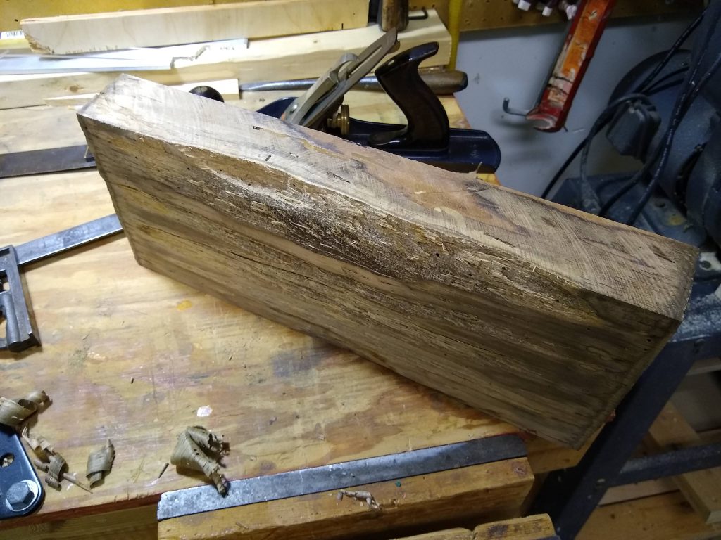
To something like this…

And I’m not done yet, this is just as far as I got before I needed to quit for the day, as you can see looking at the other side.

It took a LOT of planing before it was flat enough to safely put it on the table saw to get a square edge. This is where a roughing plane would have been a wonderful thing to have. Would have been much better off re-sawing on the band saw if it fit. Would have been a lot easier with rip blade that wasn’t fifty years old too.

So, It’s Done For Now

At least as done as I need it to be.

Not pretty, just functional

Used a piece of scrap 2×4, resawn to a little over 3/8″.

Made some slabs from an old 2×4

Planed cut smooth after each slice.

Then smoothed the rough side of each slab. My bench hook was a little too tall, so I had to shim them up with a bit of 1/4″ plywood so the plane would clear.


I held the LHSWBBT next to one of the slabs at what felt like a good angle, and ran a pencil line. Then stuck the two sides together with some double sided tape and cut on the band saw.

Cut sides on band saw and planed smooth

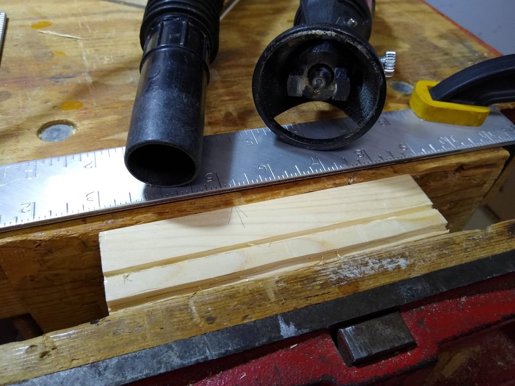
I needed rabbets and dados for the top and PCB. Started out cutting free-hand with a utility knife (they’re only about 1/8″ deep), but realized it would be a lot easier with the Dremel plus router base and a straight edge.

Pretty obvious which one was free-hand and which was done with the straight edge and Dremel

There is no pretty joinery here, or even any attempt at it. The side which supports the hand is one of the slabs laid flat and planed to the same angle as the sides. The dados hold the PCB in place and everything is held together with three screws on each side.

Almost there. Sides still need to be trimmed to length

The bottom has been left open (easy to rewire/add things if I choose). Undo the four top screws and the cover lifts off. Nothing fancy, but this thing is fully functional.

Stuff that works…

How’s It Hooked Up?

The software is here. Just a simple little hack. The final version is almost the same as what’s posted. All that’s changed is some extraneous junk has been removed, and the thumb button now acts like the left-control key on the keyboard.

And here’s a fancy hand-drawn schematic.

Here you go

The Return of the Left Hand Scroll Wheel Button Box Thingie

So, several months later… (what am I talking about?)

I finally get ’round to doing more with the LHSWBBT. Going ultra-cheap isn’t the fastest way to get something done. Do you spend $10-$15 on a part or order ten of them for $1.50 and wait 4-6 weeks for it to show up? If you’re going ultra-cheap, you take option number two.

When combined with mistakes, like not noticing the the perf-board you ordered has smaller than normal through holes, and you can’t install the PC mount switches, it takes even longer.

Putting It Together

Mounted the switches and encoder

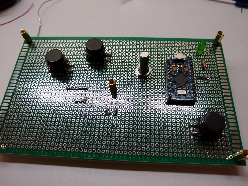
First step, mount the switches and encoder to the PC proto-board. Layout was detailed and scientific – I set my hand on a piece of paper and marked where my fingers fell. Drilled the hole for the encoder and soldered the switches to the board.

We’re committed now

I had a large sheet of acrylic in the shop suitable for the project, from which top panel was cut on the band saw. This leaves somewhat nasty edges on the acrylic, but a Stanley No.5 bench plane set for a thin cut does an excellent job of cleaning up, straightening and squaring up the edges.

I located the mounting holes for the acrylic by taping the PCB to it and drilling through the existing holes in the PCB. Then I installed extra long standoffs in PCB so the acrylic could be positioned over the mounted switches, and marked the rough center of each with a Sharpie.

Routing the holes.

Knowing I wouldn’t get the alignment close enough if I drilled final sized holes, I drilled starter holes and used a Dremel with a router base clamped upside down in the vise to open up the holes a bit at a time until they fit.

Close enough

Hooking Everything Up

I went for crude but simple, and easily modifiable. I installed Berg pins for the connections to every component and wire-wrapped the whole thing. Fast and easy, and it makes it super simple for the LHSWBBT to evolve over time.

All parts installed.

It may be ugly, but it’s fully functional.

Everything connected to Berg pins and wire-wrapped.

And yes, it does work. Still needs some updates to the software. I’ve given up on getting the Arduino library to work with more than three mouse buttons, and have decided that the thumb button would be more useful as a modifier key such as Control. I haven’t updated the Button class to be able to transmit keyboard events as yet, so the thumb button isn’t doing anything.

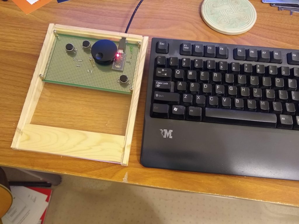
Fully functional, sans case.
As you have probably noticed, there isn’t any case for this thing yet. It’s just sitting on stand-offs. I plan on wrapping it in a wooden frame whenever I get another ’round-tuit.