
(Updated 2024.07: New design features a quick release base designed for my 4080 profile rig. Get the stl files here: https://www.printables.com/model/453287-load-cell-sim-racing-handbrake-updated-202408)
I finally got ’round-tuit. I’d picked up a 10kg load cell and HX711 load cell amplifier from SparkFun a couple of years ago, but as is often the case, multiple other shiny new projects grabbed my attention. The lack of an easy way to fabricate many of the parts had something to do with not getting ’round-tuit as well.
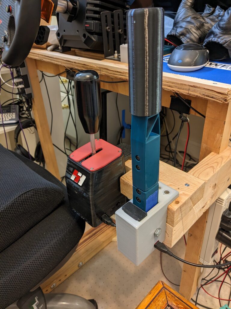
So, now that I’ve a 3D printer, I decided it was time to retire the trusty old handbrake I’d built back in 2019 and build a new one.
I soldered up the HX711, a HiLetgo Pro Micro Arduino clone (Arduino Leonardo board in the IDE), and a header for the load cell onto protoboard… and made the first mistake.
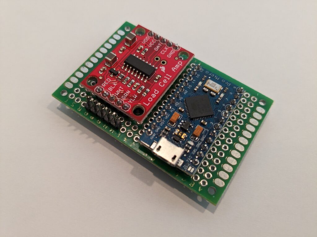
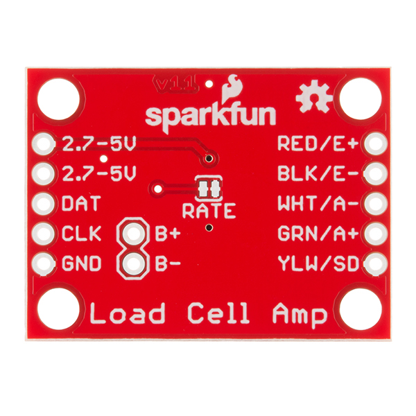
The HX711 ships jumpered to run at 10 Hz, which is fine for a scale, but way too slow for a handbrake. See that trace right above where it says “RATE”. Well, it needs to be cut to run the HX711 at 80 Hz. So, rather than desolder everything, I very carefully drilled a hole through the back of the protoboard and cut the trace. Don’t do it this way – much easier to cut it first. <g>
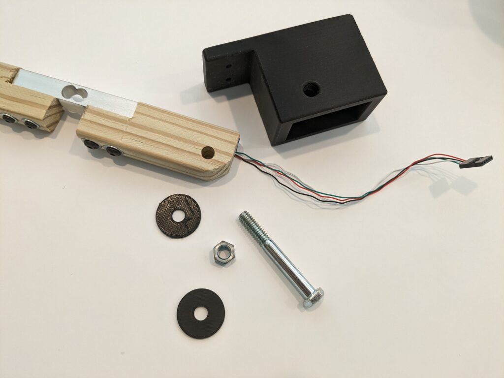
Next, I designed a test base, attached the load cell to a piece of wood, and bolted it to the rig to see if it was strong enough. Nothing broke, so I proceeded to write the code.
Testing setup
The code is nothing fancy, just used the MHeironimus Arduino joystick library and the bogde HX71 libraries. Read data, scale it, ignore low level noise, and send to the PC when the value changes.
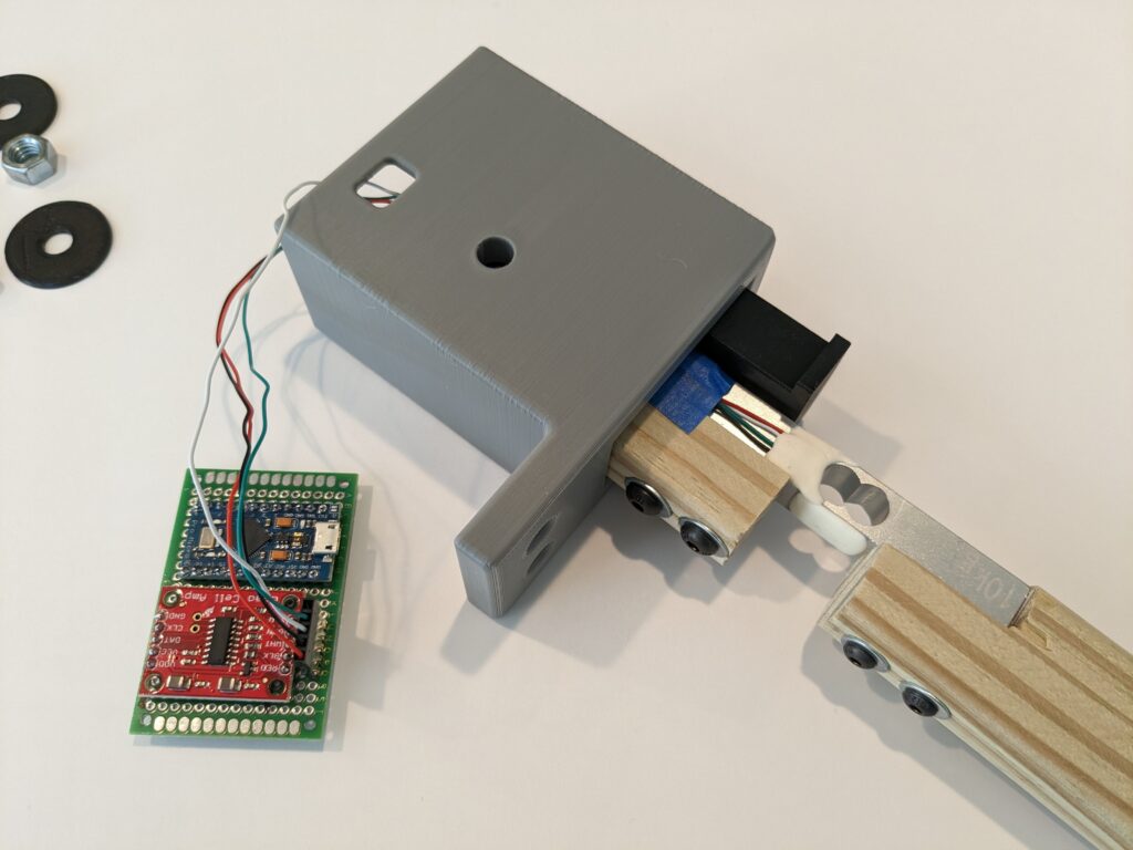
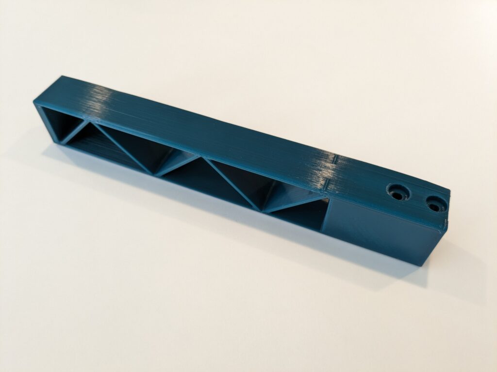
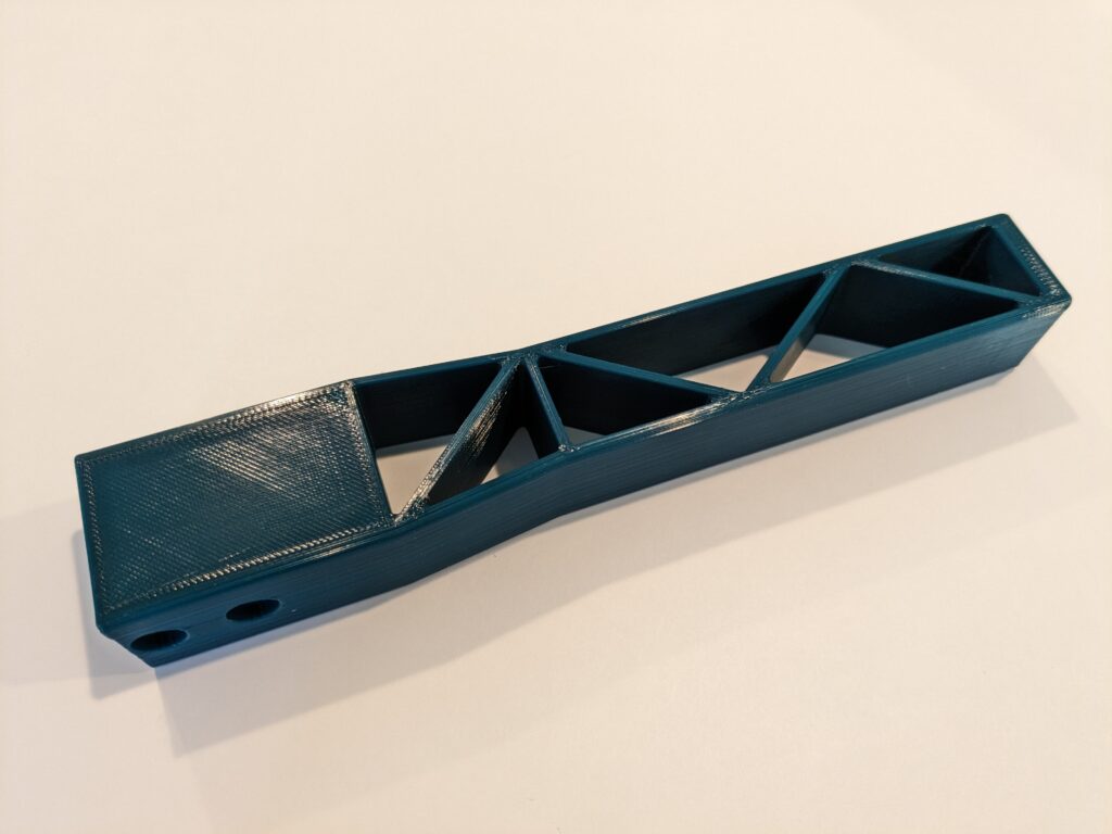
With the code and the test base working I got to designing the final base and lever. The final base included a place to mount the PCB.
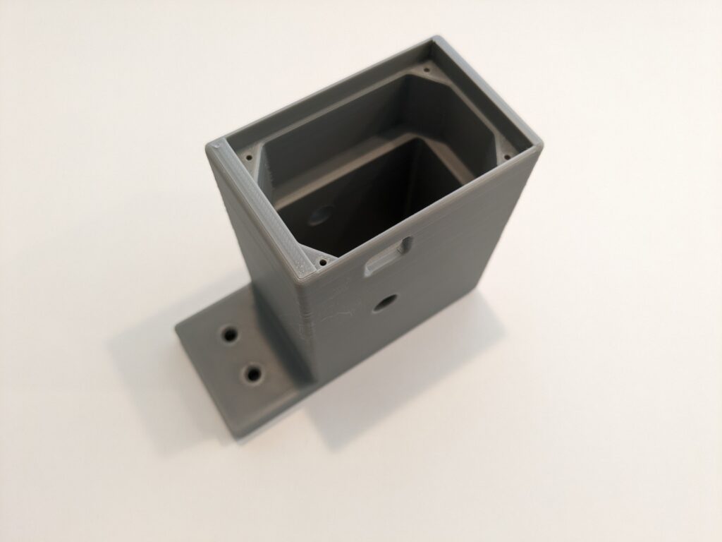
Base with PCB mount
Rather than use a spring, I printed a block of TPU which goes in front of the lever. I printed a few, changing the print density until I liked the amount of squish it provided.
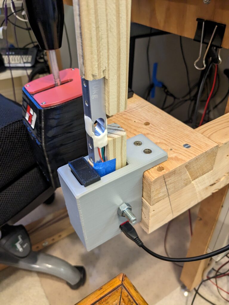
Test rig
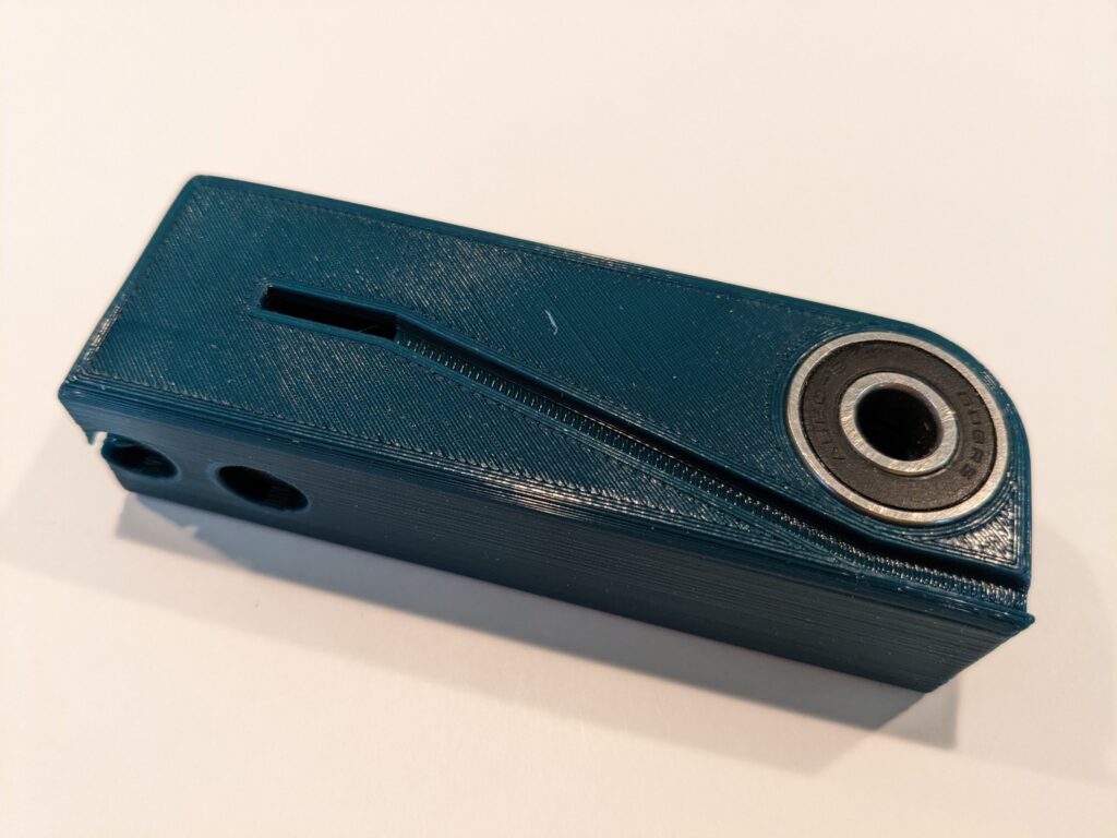
The Lever
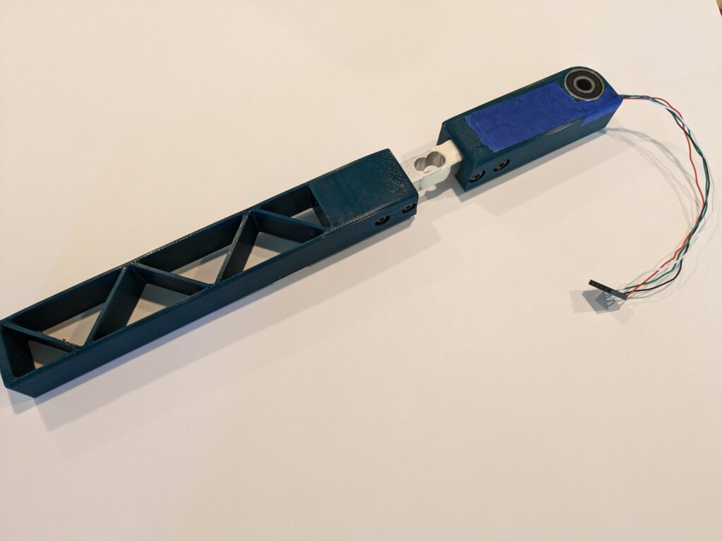
The lower part of the printed lever has a pair of press fit 608 skateboard bearings on either side to spread the load. The groove down the side is for the load cell wiring. The opening to the inside is wide enough to slip the five pin Dupont connector through.
Press fit bearings in vise
I decided the first upper lever was a bit too bulky and a bit too tall, so I made another with some taper that was a bit shorter.
Original upper lever
Tape covers wire – will hot glue later
Slimmer upper handle
The holes on the countersink side are supposed to be clearance holes. Depending on how it prints, you may have to chase them with a reamer or drill. The holes on the far side from the countersinks are supposed to be tight enough that they are threaded by the screws.
Designed and printed a grip in TPU. The grip for the first lever had a domed top, which I decided I didn’t care for, so I made the grip for the slim lever flat on top.
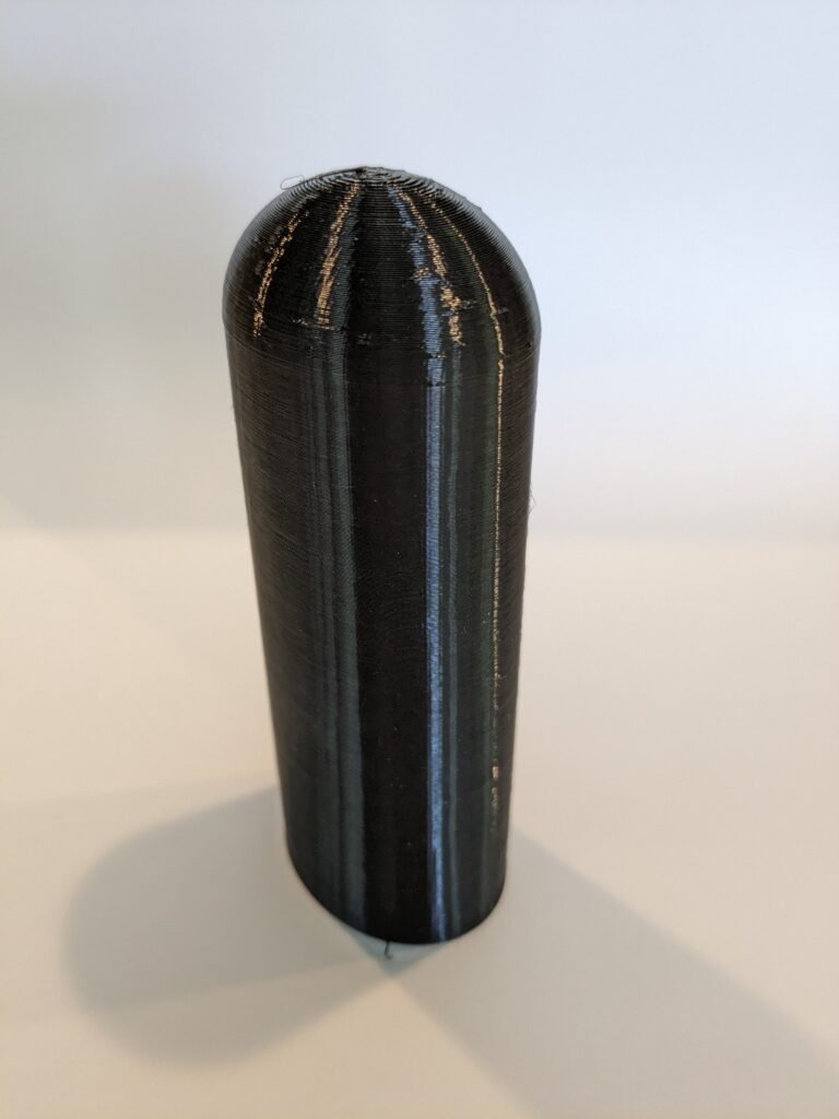
Did not like the domed top
Code
The code is quite simple. All the heavy lifting is done in the joystick and HX711 libraries. You can get a copy here – Analog-E-Brake-Load-Cell
You may be happy with the settings I used for SCALE_FACTOR and NOISE, but to determine these yourself just build with DEBUG and CALIBRATE defined. I’d initially set NOISE to 10, but discovered that the vibration of the rig while driving was enough to generate readings as high as 150, so I bumped that up to 250.
// Analog eBrake-Handbrake using hx711 to read load cell

// #define DEBUG
// #define CALIBRATE

#include "Joystick.h"	// https://github.com/MHeironimus/ArduinoJoystickLibrary
#include "HX711.h" 		// https://github.com/bogde/HX711

#define LOADCELL_DOUT_PIN  3
#define LOADCELL_SCK_PIN  2

HX711 scale;

// max joystick (32767) divided by max HX711 reading (1,000,000) by experiment
#define SCALE_FACTOR	0.032767

// noise level determined by experiment, DEBUG & CALIBRATE defined
#define NOISE 		250

#define BUTTONS		0
#define HATS		0

Joystick_ Joystick(JOYSTICK_DEFAULT_REPORT_ID, JOYSTICK_TYPE_JOYSTICK, BUTTONS, HATS,
	false, false, false, false, false, false, false, false, false, true, false);
//  X      Y      Z      Rx     Ry     Rz     Rudder Throt  Accel  Brake  Steering

long offset;

void setup()
{
	Joystick.setBrakeRange(0, 32767);
	Joystick.begin();
	#if defined(DEBUG)
	Serial.begin(115200);
	#endif

	scale.begin(LOADCELL_DOUT_PIN, LOADCELL_SCK_PIN);

	offset = scale.read_average(10);	// zero out offset at startup

	Joystick.setBrake(0);		// start at zero brake
}

#if defined(CALIBRATE)
	long reading = 0;
#endif

long lastVal = 0;

void loop()
{
	if (scale.is_ready()) {
		long mapped = (long)((float) (abs(scale.read() - offset)) * SCALE_FACTOR);

		if (mapped > 32767)
			mapped = 32767;

		#if defined(CALIBRATE)
		/* calibration:
		 NOISE
		 Power up with no pressure on the cell, wait a bit and record the noise level. Note
		  that it is very sensitive - it will pick up vibrations of your rig. You might wish
		  to drive a bit with the calibration code running. Update NOISE value.

		 SCALE_FACTOR
		 Apply reasonable pressure on lever. If it maxes out (32767) too easily change
 		 SCALE_FACTOR to bring it in range.
		*/
		if (mapped > reading) {
			reading = mapped;
			Serial.print("Value: ");
			Serial.println(reading);
		}
		#else
		if (mapped <= NOISE)
			mapped = 0;
		if (lastVal != mapped) {		// don't transmit data unless changed
			Joystick.setBrake(mapped);
			lastVal = mapped;
		}
		#endif
	} else {
		delay(1);
	}
}
Parts
- 60 x 40 mm proto PCB
- HiLetgo Arduino Pro Micro clone (https://tinyurl.com/3md9wk75)
- HX711 load cell amplifier (https://www.sparkfun.com/products/13879)
- 2 608 roller skate bearings
- 10 Kg load cell (https://www.sparkfun.com/products/13329)
- 2″ 5/16 bolt and nut
- 2 M4x30 screws
- 2 M5x30 screws
Model Files
The model files are available at Printables.com