
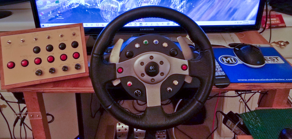
I’ve never been completely satisfied with my home brew button box. There’s nothing wrong with it, it works just fine, but hitting the wrong button or running off the road while looking for the right one was getting old, so I started designing a mod for my G25 (yeah, I know, ancient… mine is fourteen years old) to add buttons right at my fingertips.
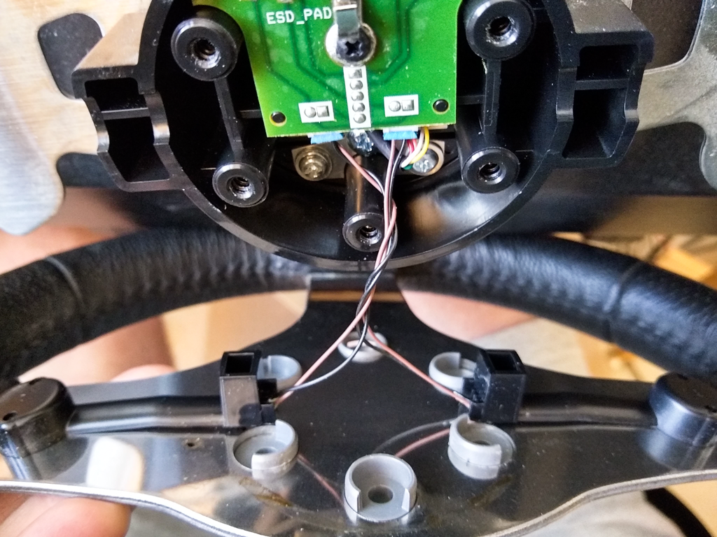
First thing to figure out is how to attach a plate to the wheel hub. There isn’t a heck of a lot of room and wanting to keep the original buttons, I had to accommodate them in the design.
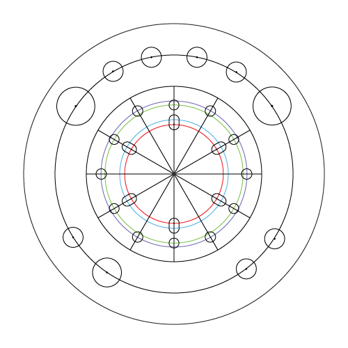
Digging around on the web I located a template for a wheel adapter that allowed standard automotive steering wheels to be bolted onto a G25. I figured out what I wanted the maximum diameter to be and added that circle to the template. Then added a properly scaled photo of the actual wheel to another layer, added a center line for the buttons, and laid out the locations for nine push buttons and a rotary encoder.
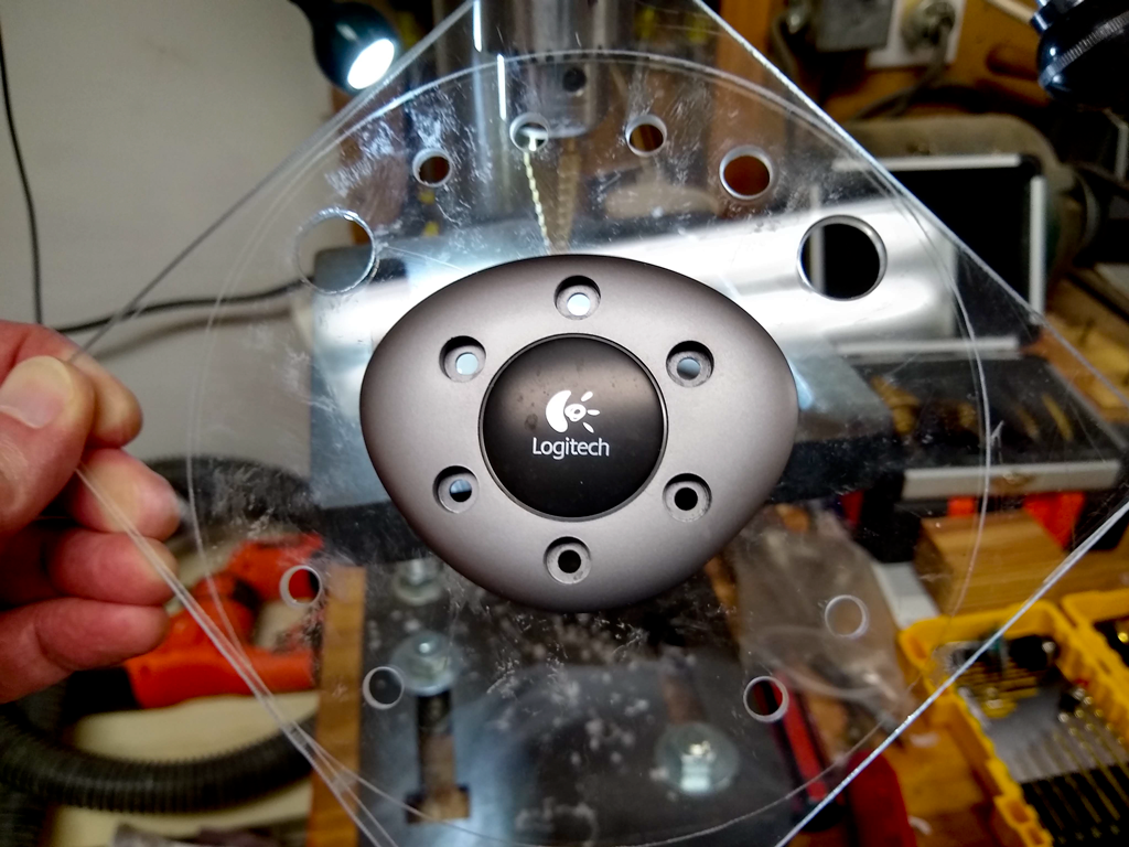
Then it was off to the shop, where I grabbed a scrap of sheet plastic, cut off a square on the band saw, and glued on a printed copy of the template.
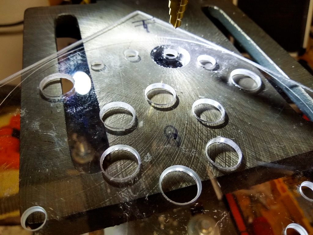
I used a step drill for all the holes, then checked the fit of the hub cover.
Then things got a bit ugly.
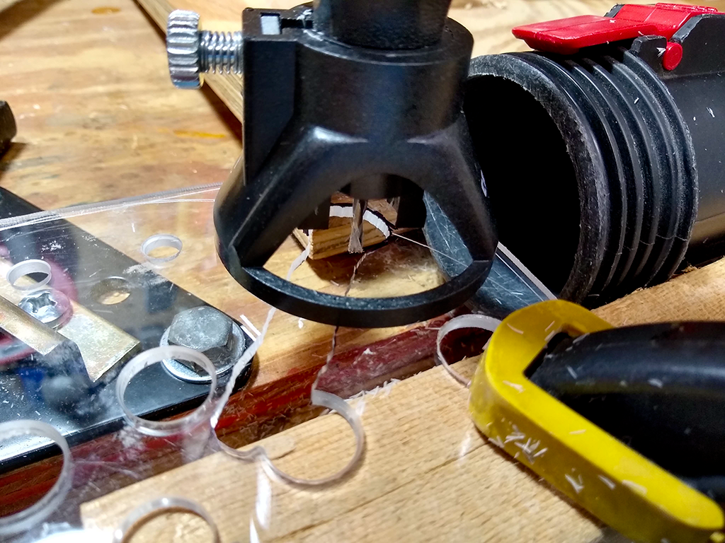
I needed space for the original switches and their wire covers. This would have looked a lot better if I’d taken the time to do a layout and cut it on the band saw, but I just threw a carbide routing bit into the Dremel and went at it. It’s all hidden behind the wheel where you have to look hard to see it’s a hack job. Good enough for me.
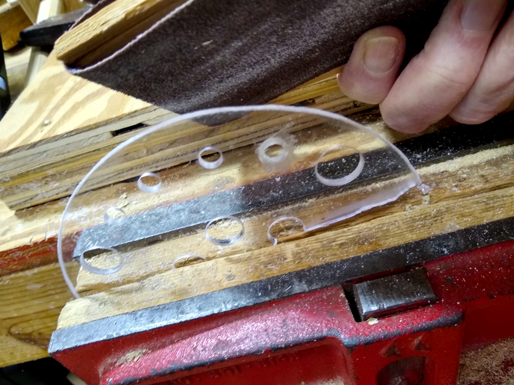
It was then rough cut on the band saw and sanded to the line I’d scribed with a compass earlier.
Threw a couple switches on it and did a full test fit. Good enough to go to paint.
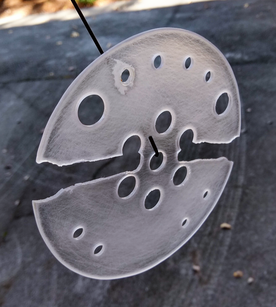
All sanded and ready to paint. No, it’s not perfectly round, but it’s close enough for me. And yes, that is a sloppy fill job where I’d gone one step too far on the bit on the first hole I drilled.
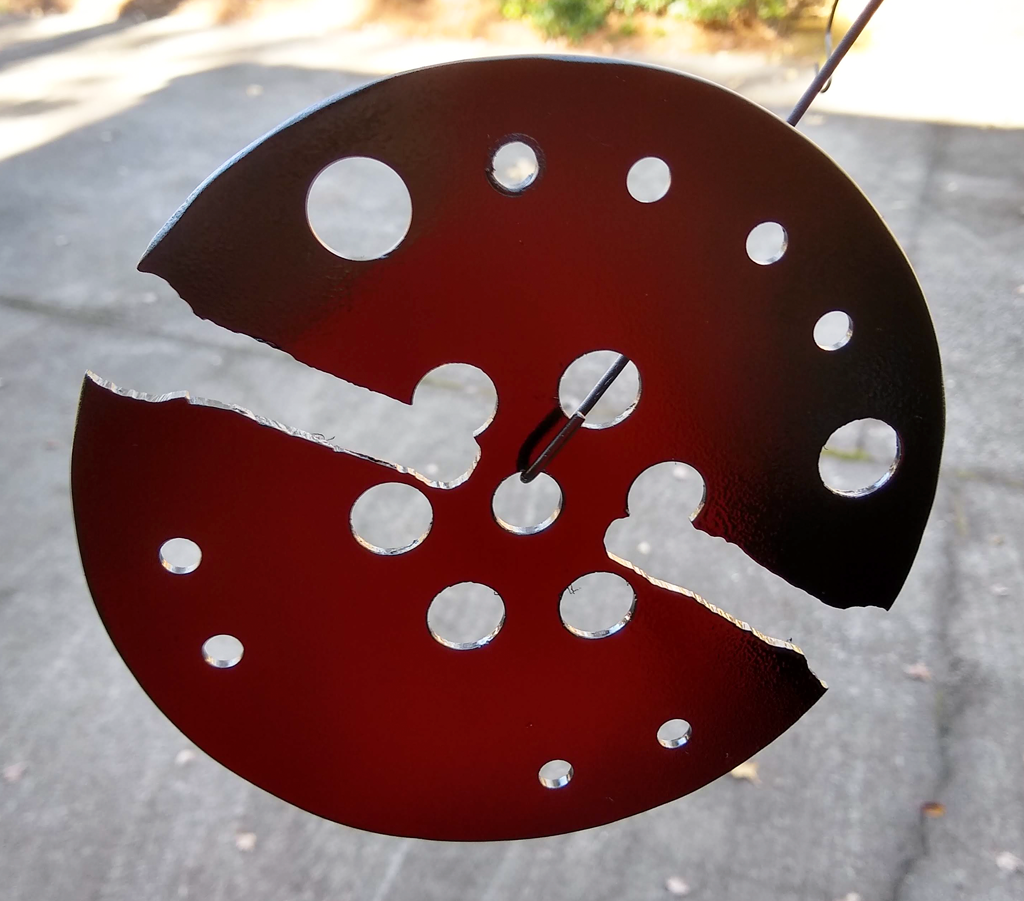
Applied light coats and managed to avoid any horrific runs in the paint. I went light enough you can still see some light through the first coat of flat black paint. The red is the light reflecting from my red t-shirt.
Interlude…
Right in the middle of the build, I was reminded why I’m doing this. Two laps from the end of a league race at Barber Motorsports Park, having chased down second place, running less than a second behind, I reached over to the button box to remove a tear-off so I could see, and hit the pit speed limiter instead. Took me a couple seconds to figure out what I’d done, and toggle it back off, but by then 2nd was long gone. Yeah, I’m really looking forward to having the controls I need during a race right under my fingertips instead of on the box on my left.
…back to the build.
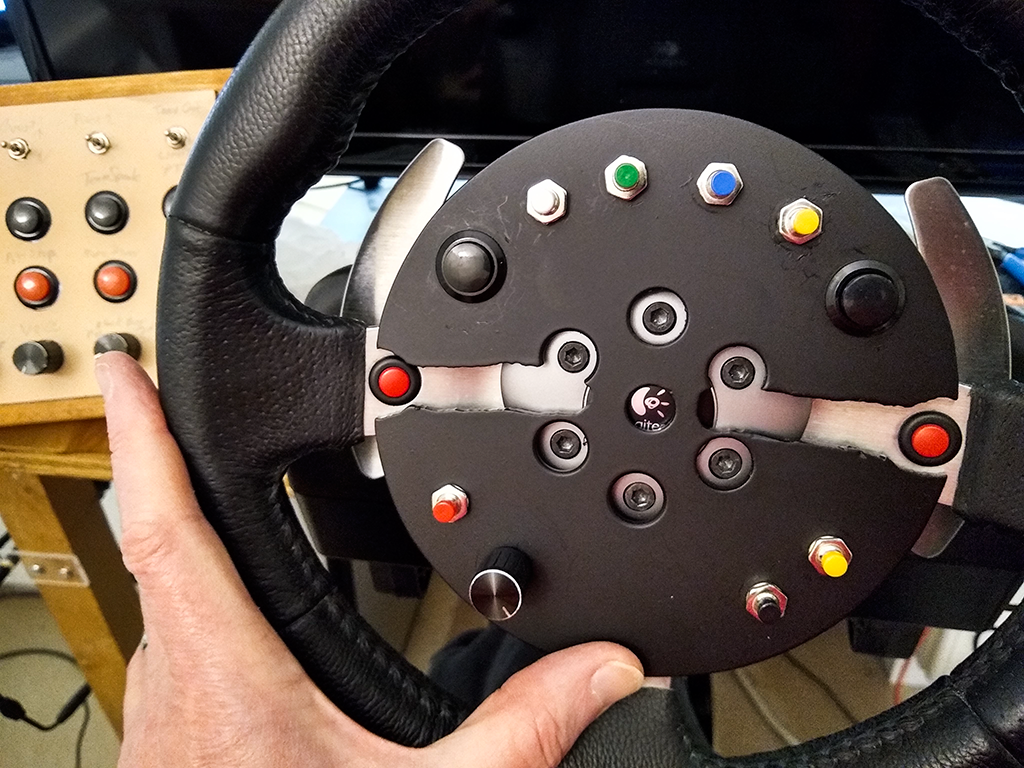
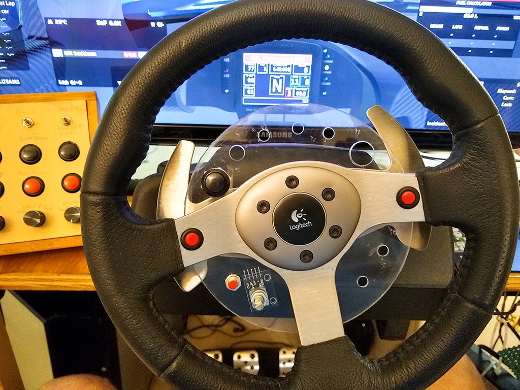
And it’s painted, with all the buttons and encoder installed. Looks a bit weird in front of the wheel, but I wanted to get an idea how it was going to look when completed.
Time to start writing the code. Not all that much to it really, as three libraries do all the heavy lifting. I used Mark Stanley’s Keypad library, Paul Stoffregen’s Encoder library, and the Joystick library by Matthew Heironimus. The project is available on my github.
I built this using PlatformIO IDE running on top of Microsoft’s Visual Studio. If you do any Arduino development using the Arduino IDE you really should check out PlatformIO – it is so much better.
#include <Arduino.h>
#include <Keypad.h>
#include <Encoder.h>
#include "Joystick.h"

//#define DEBUG
//#define TESTING

Joystick_ Joystick(JOYSTICK_DEFAULT_REPORT_ID,
  JOYSTICK_TYPE_GAMEPAD, 12, 0,
  false, false, false, false, false, false,
  false, false, false, false, false);
//Joystick_ Joystick();

const byte ROWS = 3; //four rows
const byte COLS = 3; //three columns
char keys[ROWS][COLS] = {
// original key map
//  {0,1,2},
//  {3,4,5},
//  {6,7,8}
// remapped to put keys in order I preferred
  {4,7,1},
  {5,6,2},
  {3,8,0}
};
byte rowPins[ROWS] = {4, 3, 2}; //connect to the row pinouts of the kpd
byte colPins[COLS] = {7, 6, 5}; //connect to the column pinouts of the kpd

Keypad kpd = Keypad( makeKeymap(keys), rowPins, colPins, ROWS, COLS );

Encoder myEnc(0, 1);
// encoder button & directions
const int encoderButton = 9;
const int counterClockwise = 10;
const int clockwise = 11;

const byte encSwitch = 9;
int lastButtonState = 0;
int buttonState = 0;
int debounceCount = 0;
const int buttonDebounce = 4;

#ifdef DEBUG
String msg;
#endif

long oldPosition  = -999;

void setup() {
    Serial.begin(115200);
    Joystick.begin();
    pinMode(encSwitch, INPUT);
    #ifdef DEBUG
    msg = "";
    #endif
}

void loop() {
    void joystickToggle(int button);

    // Fills kpd.key[ ] array with up-to 10 active keys.
    // Returns true if there are ANY active keys.
    if (kpd.getKeys())
    {
        for (int i=0; i<LIST_MAX; i++)   // Scan the whole key list.
        {
            if ( kpd.key[i].stateChanged )   // Only find keys that have changed state.
            {
                if (kpd.key[i].kstate == PRESSED) {
                    Joystick.pressButton((int) kpd.key[i].kchar);
                    #ifdef DEBUG
                        msg = " PRESSED.";
                    #endif
                } else if (kpd.key[i].kstate == RELEASED) {
                    Joystick.releaseButton((int) kpd.key[i].kchar);
                    #ifdef DEBUG
                        msg = " RELEASED.";
                    #endif
                }
#ifdef DEBUG
                Serial.print("Key ");
                Serial.print((int) kpd.key[i].kchar);
                Serial.println(msg);
#endif
            }
        }
    }

    // read rotary encoder
    long newPosition = myEnc.read();
    const int countDiv = 3;
    if (newPosition != oldPosition) {
        if (newPosition > (oldPosition + countDiv)) {
            joystickToggle(counterClockwise);
            oldPosition = newPosition;
            #ifdef DEBUG
            Serial.println(newPosition);
            #endif
        } else if (newPosition < (oldPosition - countDiv)) {
            joystickToggle(clockwise);
            oldPosition = newPosition;
            #ifdef DEBUG
            Serial.println(newPosition);
            #endif
        }
    }

    // read rotary encoder switch
    buttonState = digitalRead(encSwitch);
    if (buttonState != lastButtonState) {
        if (++debounceCount > buttonDebounce) {
            if (buttonState == 0) {
                Joystick.pressButton(encoderButton);
                Serial.println(" PRESSED.");
            } else {
                Joystick.releaseButton(encoderButton);
                Serial.println(" RELEASED.");
            }
            lastButtonState = buttonState;
            debounceCount = 0;
        }
    }
}  // End loop

#ifdef TESTING
const int delayTime = 200;      // slow it down so I can see it onscreen
#else
const int delayTime = 12;
#endif
void joystickToggle(int button) {
    Joystick.pressButton(button);       // button pressed
    delay(delayTime);
    Joystick.releaseButton(button);       // button released
}
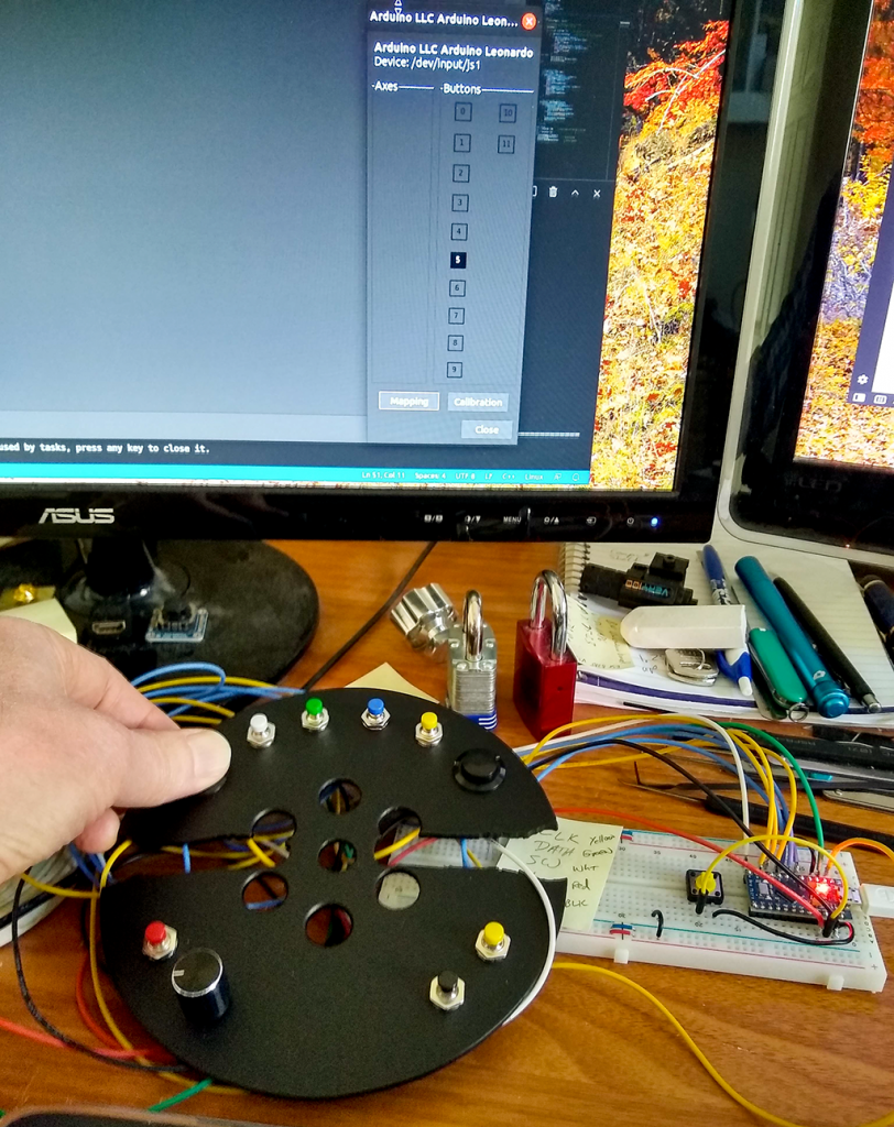
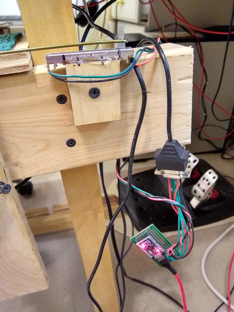
Wired it up on my desk for testing.
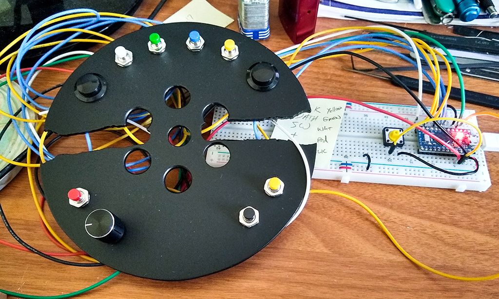
And, after fixing my stupid mistakes, it works!
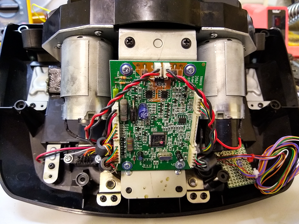
Now the “fun” part – stuffing this all into the G25 wheel base. For some reason, the folks that designed the G25 did not put “make it easy to add additional hardware” very high on their list.
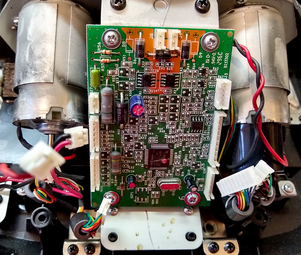
Buried way down under all this is the opening through which the wires have to be run.
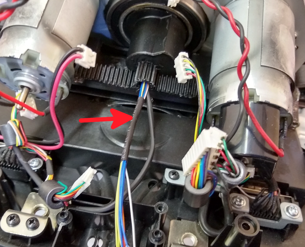
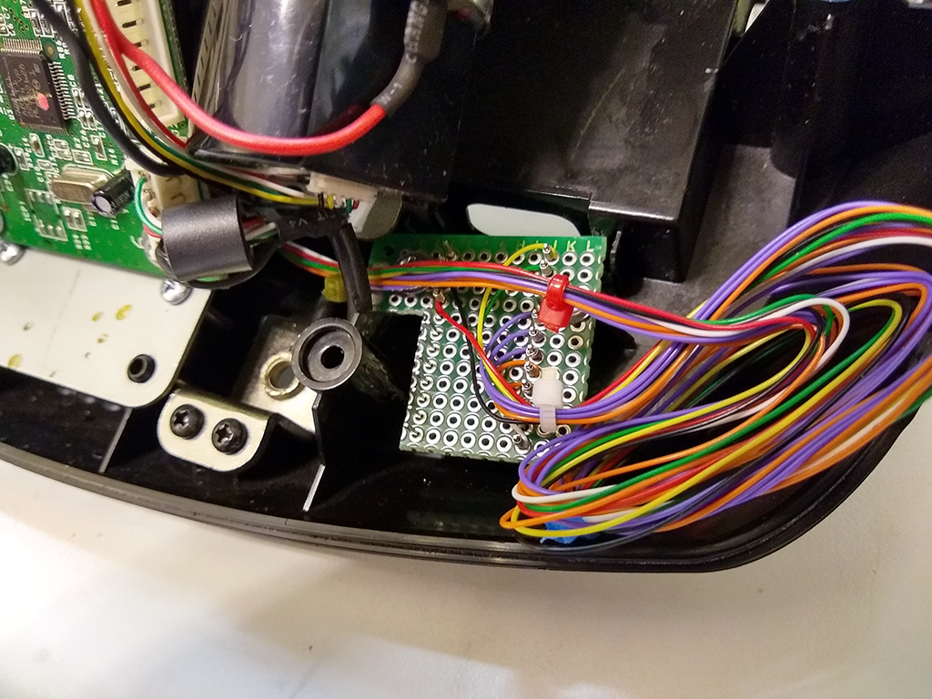
Note the heat shrink I used for wire management the first time around. This will come back to haunt me.
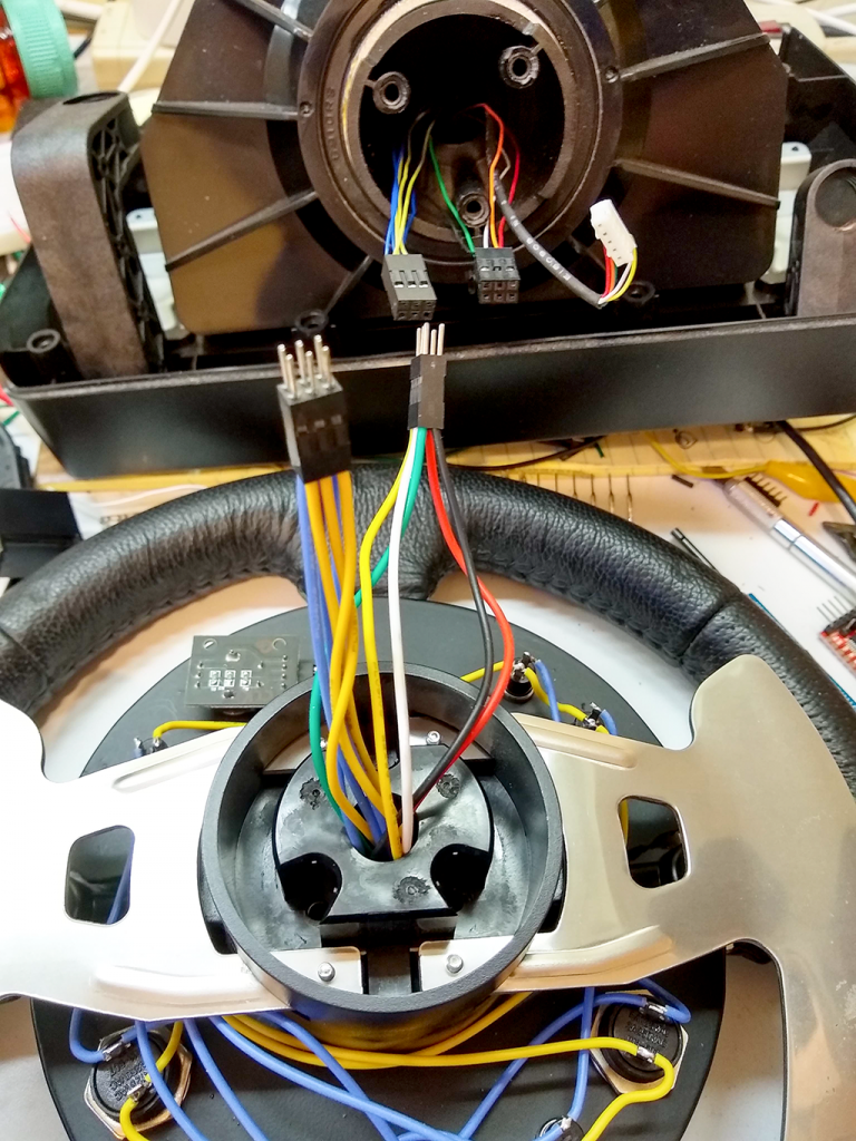
I used 22 AWG stranded wire where it was exposed, but had to use 30 AWG wire wrapping wire to allow so many wires to fit through the opening in the base.
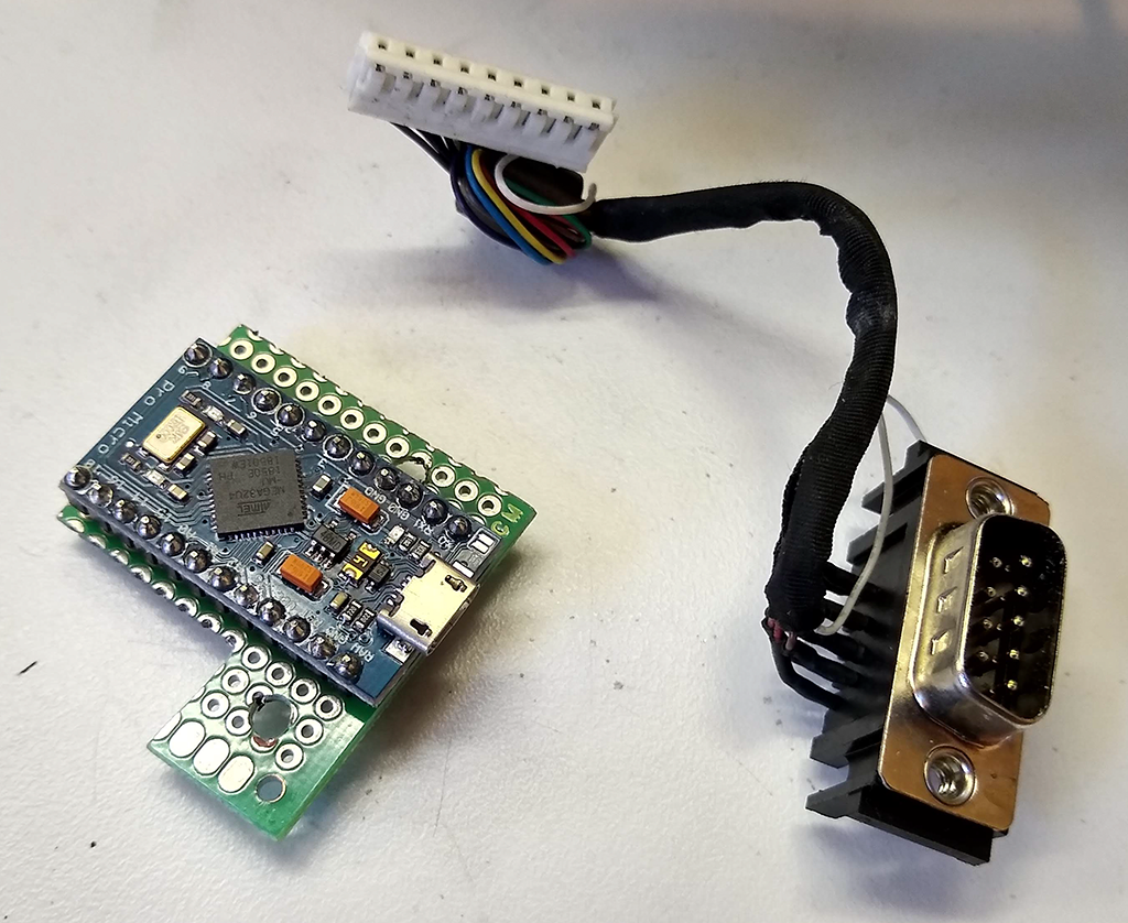
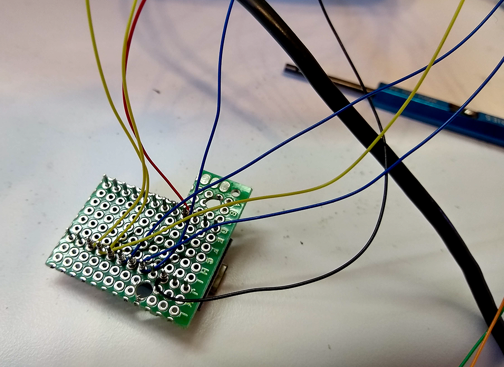
The original G25 shifter stopped working and was replaced a couple of years ago, so the location of the DB9 for the shifter seems like an excellent place to install the proto board mounted Arduino (used a generic HiLetGo branded Pro Micro – $5 each in lots of three on Amazon – even cheaper if you’re willing to order from China and wait).
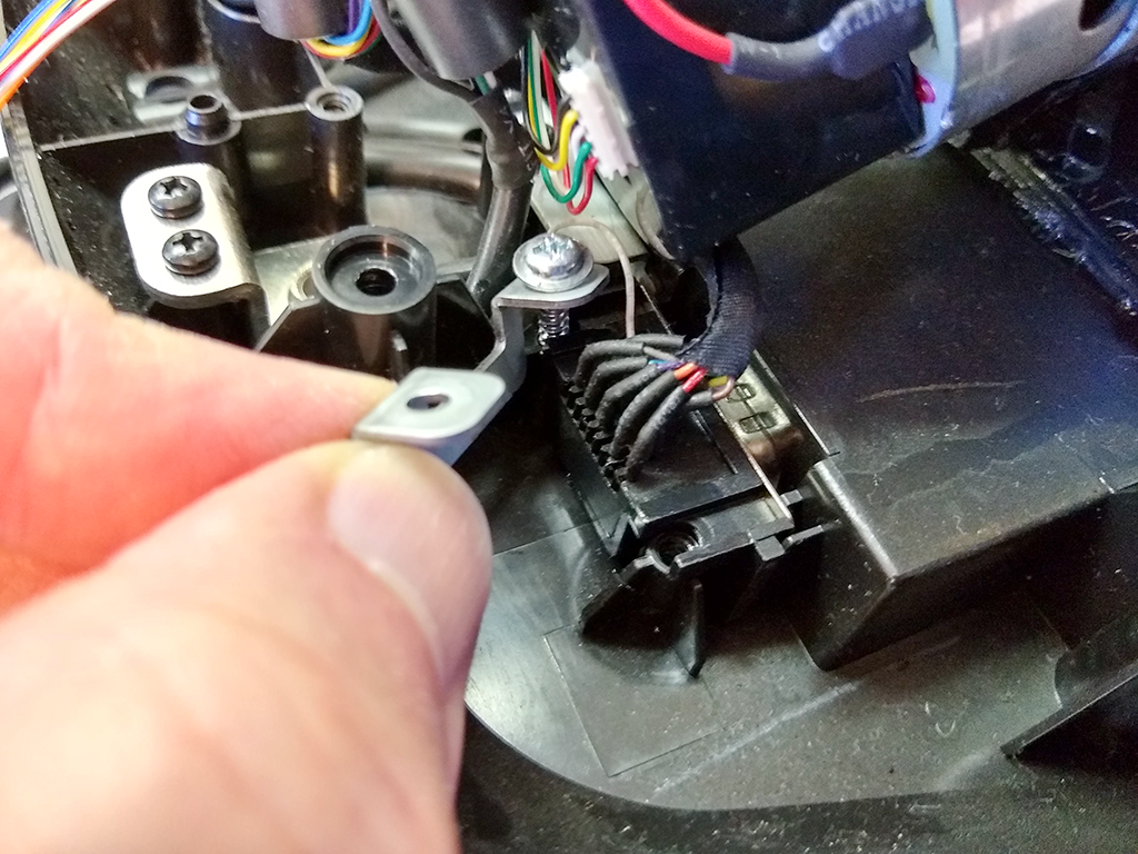
Pulled the old connector and cable.
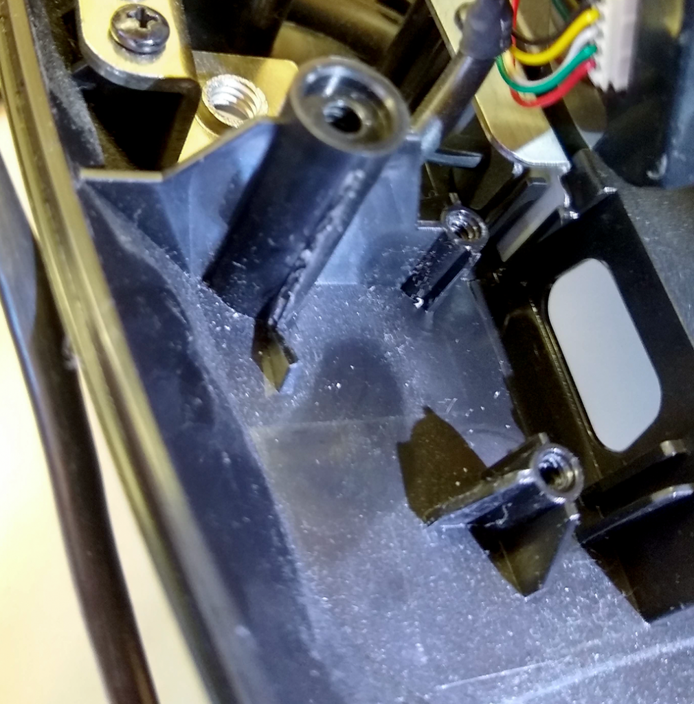
Trimmed away some unneeded plastic to make some room.
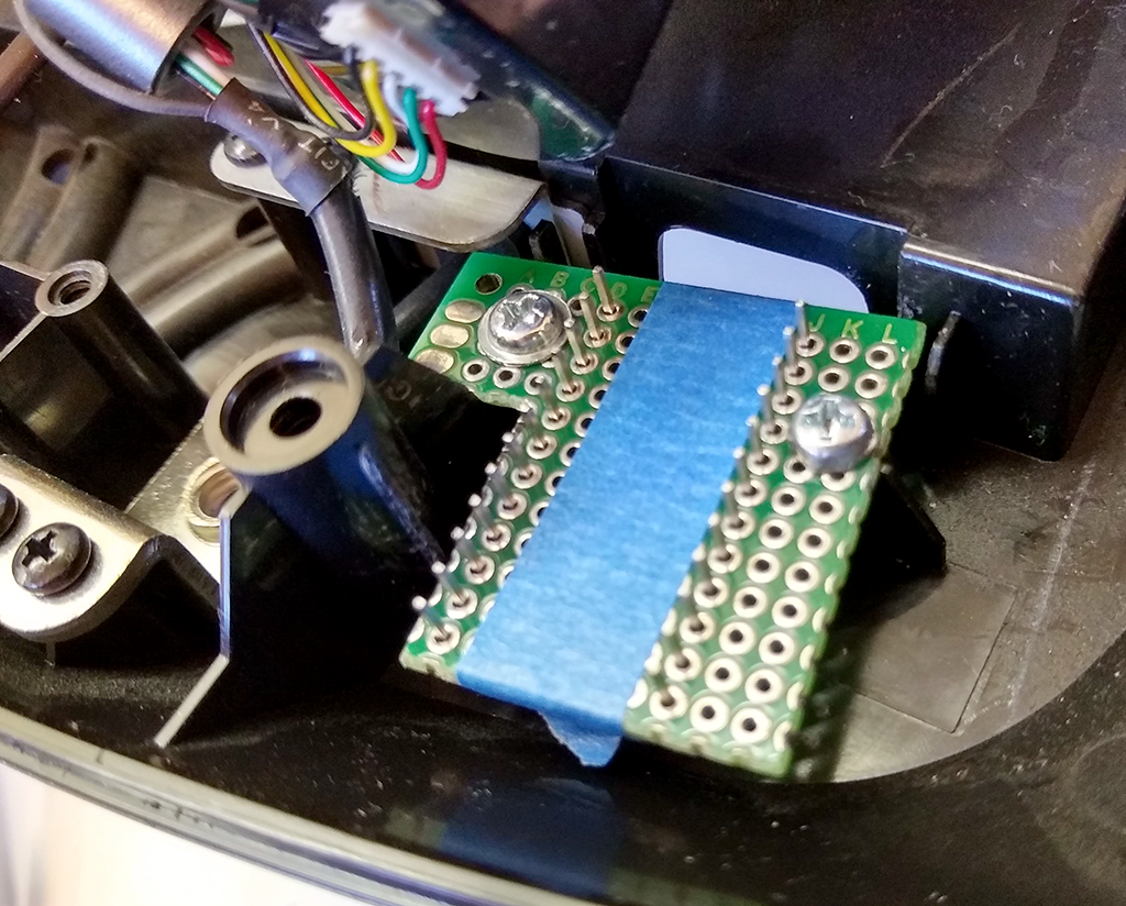
And the Arduino is fitted up and ready to be wired.
Then I wire wrapped all the switches to the Arduino and completely reassembled the wheel before starting final testing. Did you notice I said completely reassembled before testing? Three of the buttons registered as two simultaneous button presses on the computer. Pull out the DVM and sure enough, two of the six wires used for the keypad scanning are shorted together.
Completely disassemble the wheel again. This is not a five minute job… closer to half an hour, or more. Remember that red arrow? Seems I got a bit carried away shrinking that heat shrink tubing and melted the insulation on the wire wrapping wire. I forgot how much easier it was to melt than normal wire insulation.
Pulled all the wire wrapping wire out, de-wired the Arduino, and started all over again, from crimping on the Dupont connector pins all the way to rewiring the Arduino. Decided not to melt the insulation again, using small cable ties this time instead of the shrink wrap.
Yes, there is quite a bit of extra wirewrap wire. There are enough unused inputs on this Arduino to connect the pedals and hand brake, which are currently hooked up to another Arduino hanging off the side of the rig. Wirewarp wire is rather brittle and tends to break when you unwind it, so you need start with a freshly stripped bit every time. I’ve left enough here to allow the wires to be moved several times. The last thing I want to do is rip the wheel completely apart to run new wire.
And… everything works!
